Hi,
But the problem is i have a 36-0-36 v ac 1000va transformer and the max voltage for TDA7293 is +-50v dc
Add extra turns in series with the primary. That will bring the voltage at the secondary down. Add only one or two at a time to tune the voltage, making sure the phasing is right. On the final build, make sure the turns are evenly spread. Use fully insulated solid core wire for safety, with as high a temperature rating as practical - #12 or #10 THHN is fine.
If the trafo is potted, you're screwed and you'll have to build a regulator.
Lies and damned lies.and you did not know until i posted the datasheet....")
I looked up the datasheet before I attempted to assist the enquirer with his problem.
The datasheet and for the ..94 are in my documents even though I have never bought, nor used a TDA chipamp.
Doable, but at the primary it will be rather laborious.Add extra turns in series with the primary. That will bring the voltage at the secondary down.
Regarding the regulation, an interesting option is to regulate before the filtering.
The regulation is less tight than for a conventional downstream regulator, which is unimportant in this case, but it has the advantage of wasting 40% less power in the ballast and of letting the amplifier benefit from the big filter cap.
It is demanding on the SOA of the pass element though, but it can be made to work, I have already designed such a PSU.
Another "creative" option is to use this circuit:
http://www.diyaudio.com/forums/powe...-elegant-insane-way-converting-220v-110v.html
By adjusting the conduction angles, any voltage can be created.
It also has side benefits of reducing the losses and the ripple.
Lies and damned lies.
I looked up the datasheet before I attempted to assist the enquirer with his problem.
The datasheet and for the ..94 are in my documents even though I have never bought, nor used a TDA chipamp.
then why did you not say earlier that the chip is 120volt capable if you knew?
The chip is not 120Vdc capable.
The max is stated in the datasheet as +-50Vdc, not +-60Vdc.
This MOSFET chip is far easier on heat issues than similar BJT chip amps. No second breakdown. For PS above +/-50V, once the speaker load get below 6 Ohm, and with transformer capable of high current, the heat can easily jump over 70 celcius. But the chip can withstand, or have internal thermal shutdown protection around 150 celcius. This tells that from heat issue, the heatsinking and fan can improve the maximum PS voltage applicable.
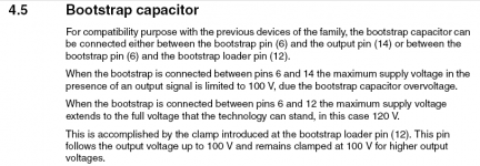
Furthermore, effect of bootstrap capacitor voltage can be limited to 100V so that PS can be applied up to 120V, by using the standard bootstrap configuration.
Attachments
good post Jay, i'd suppose the vendor will not put the 120volt figure in their data sheets if that is not applicable.....
otoh, some would like to operate their chips below maximum rail specs which is a prudent thing to do....but since we are discussing posibilities, we have to put faith in the manufacturer since they are supposed to know what they are doing...
otoh, some would like to operate their chips below maximum rail specs which is a prudent thing to do....but since we are discussing posibilities, we have to put faith in the manufacturer since they are supposed to know what they are doing...
317 regs
2) On the output use NO MORE than ONE 100uF capacitor Directly after the rectifier use as large as you like 10 000uF would be sufficient. Remember to fit the small caps as specified +- 0.1 uF or so on THE PINS of your regulator I.C. to combat hash noise
I hope this helps

1) The 35 volts quoted above is the DIFFERENCE between in/output rather use the LM338Ksteel as it can handle the current of 5 amps If you use the LM317T REMEMBER the power that can be absorbed is FIFTEEN (15) watts only. I read this in an old Popular Television of 1990 vintage. The manual tell you that power and current is internally protected and this lead to funny behaviour of the I.C. when the limits are exceeded and this means nothing really I also deducted this when I studied the specs of the different packages at the back of a transistor manual.Do not try the LM317 for 45 volts output. It will get damaged as it can withstand 35 volts across itself.
At power-on, there will be zero volts at the output.
Search for transistor assisted zener regulator.
Gajanan Phadte
2) On the output use NO MORE than ONE 100uF capacitor Directly after the rectifier use as large as you like 10 000uF would be sufficient. Remember to fit the small caps as specified +- 0.1 uF or so on THE PINS of your regulator I.C. to combat hash noise
I hope this helps
Doable, but at the primary it will be rather laborious.
10 or 15 turns wrapped around the outside? Piece of cake. I wasn't suggesting taking it apart.
Regarding the regulation, an interesting option is to regulate before the filtering.
The regulation is less tight than for a conventional downstream regulator, which is unimportant in this case, but it has the advantage of wasting 40% less power in the ballast and of letting the amplifier benefit from the big filter cap.
It is demanding on the SOA of the pass element though, but it can be made to work, I have already designed such a PSU.
Most of the old HP lab power supples used a similar technique - but using SCR's for two legs of the rectifier. Since SCRs have high surge current capablity it's not challenging to the SOA at all. Schematics for those old power supplies are probably still available.
With a 230V primary I am afraid it will take more than 15 turns to significantly alter the voltage, even with a 1KVA transformer.10 or 15 turns wrapped around the outside? Piece of cake. I wasn't suggesting taking it apart.
Measure the no load primary current.
Add on your extra primary turns. Attach them in phase! This will result in a lower secondary voltage. If you connect the extra turns out of phase the secondary voltage will go higher. Be careful and check.
Now go back and measure the no load primary current. You will find it has dropped significantly. The more turns you add, the more the primary no load current drops. The transformer runs cooler and it also runs more efficiently at low and medium duty loadings. Better for the planet and better for your electricity bill.
I agree with Elvee you need a lot of turns extra on the primary in post #25 I suggested adding a few counter turns to each secondary, here 10 - 15 turns may be enough (rule of thumb is 2-3 turns per volt). When you counter turn it subtracts voltage. In other words if the secondary is clock-wise then counter clockwise the turns, This is the normal to quickly match a transformer to the required voltage. You either add windings in phase (add voltage) or subtract windings counter phase (reduce voltage)With a 230V primary I am afraid it will take more than 15 turns to significantly alter the voltage, even with a 1KVA transformer.
Nico is right about the direction of the turns in the secondary.
But it is true that they will just adjust the voltage, not reduce the iron losses, and they will increase the copper losses, like any additional winding.
For a transformer of this size, the turns/volt is more like ~1, but if you want to remove 15% from a 240V primary, it will be no menial job, especially considering the gauge of the wire you have to use.
With a 230V primary I am afraid it will take more than 15 turns to significantly alter the voltage, even with a 1KVA transformer.
i attach data for a 1kva torroid, Toroidal Core PN# 100 , turns per volt is 0.423 so that 15 turns is 6.23 volts, about 20plus turns will be about right..
For the secondaries, yes. At the primary it's another story.i attach data for a 1kva torroid, Toroidal Core PN# 100 , turns per volt is 0.423 so that 15 turns is 6.23 volts, about 20plus turns will be about right..
For the secondaries, yes. At the primary it's another story.
turns per volt is a constant based on cross section area @60Hz, 15KiloGauss...........you can use it to determine either primary turns or secondary turns....
Yes, but what I mean is that to remain reliably under 50V for all conditions including quiescent, the OP will need to reduce the voltage by 20% at least, and that will translate into more than 100 turns. That is why I say it is unpractical.turns per volt is a constant based on cross section area @60Hz, 15KiloGauss...........you can use it to determine either primary turns or secondary turns....
- Status
- This old topic is closed. If you want to reopen this topic, contact a moderator using the "Report Post" button.
- Home
- Amplifiers
- Power Supplies
- +-45vdc regulated power supply schematics needed.