I've completed the first rev of the board design. I decided to base the power supply section design on the PS from my headphone amplifier board, so it requires a dual secondary transformer (not center tapped). You can take off DC power from a terminal block and use it to power other boards, should you use any.
I came up with a nice compact layout for each channel of the gain stage circuit. I implemented a separate ground plane under each channel and tied that back to the main ground.
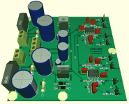
See screen shot of the board mockup from my PCB layout software, Target3001, below. I plan to order some prototype boards soon.
I came up with a nice compact layout for each channel of the gain stage circuit. I implemented a separate ground plane under each channel and tied that back to the main ground.
See screen shot of the board mockup from my PCB layout software, Target3001, below. I plan to order some prototype boards soon.
Attachments
It will take at least a week to get the boards back from the fab and build and test one.
Assuming there are no problems, I plan to offer both the bare board with a bill of materials that are needed to build it, or populated and tested board. You will also need an appropriate transformer to power the board.
If there is more interest after the board is checked out I could offer a group buy.
It will take at least a week to get the boards back from the fab and build and test one.
Assuming there are no problems, I plan to offer both the bare board with a bill of materials that are needed to build it, or populated and tested board. You will also need an appropriate transformer to power the board.
If there is more interest after the board is checked out I could offer a group buy.
I wanted to follow up by saying that one of the nice aspects of the board design is that the power supply is configured to use a dual secondary transformers OR two single secondary transformers. Often times you can find great deals on transformers having low VA and a 12Vac secondary. These have poor regulation, which typically means that the unloaded voltage is several volts higher. This is perfect for using with this board's power supply to create +/- 14-15Vdc rails if you use two of them. Often times low VA 15Vac transformers actually give too high a secondary voltage under light loading. As long as you are only powering the gain stage board, the 12Vac low VA option is better.
For instance, I have just ordered a couple of these transformers to try out:
Power Transformer | 28-0010 (280010) | Distributed By MCM
$3.75 each if you order four! Rated 12.6V@1.2Amp with 117VAC on primary.
It looks like the PCBs are finally en route and should arrive Monday. I will try to build up and test a board next week once I have all the parts in hand. I have a lot of other stuff going on in the next couple of weeks, but optimistically I should be able to get one tested out and the results posted.
For instance, I have just ordered a couple of these transformers to try out:
Power Transformer | 28-0010 (280010) | Distributed By MCM
$3.75 each if you order four! Rated 12.6V@1.2Amp with 117VAC on primary.
I finally received and tested these little transformers. Just as I suspected, with no load on the secondary and 120VAC feeding the primary I get 15.95Vac across the full secondary winding even though the transformer is advertised as having 12.6Vac. The low VA rating means regulation is very poor. Another way to say this is that the no-load and loaded (with rated load) secondary voltages are more than about 10% different (its 27% in this case). This is perfect for a 15Vdc regulated supply that has to power only a few op-amps.
I finally received and tested these little transformers. Just as I suspected, with no load on the secondary and 120VAC feeding the primary I get 15.95Vac across the full secondary winding even though the transformer is advertised as having 12.6Vac. The low VA rating means regulation is very poor. Another way to say this is that the no-load and loaded (with rated load) secondary voltages are more than about 10% different (its 27% in this case). This is perfect for a 15Vdc regulated supply that has to power only a few op-amps.
How many boards do you suppose one supply would power? Just the one?
How many boards do you suppose one supply would power? Just the one?
The regulators are capable of over 1A each if you heatsink them and use a capable transformer. That can easily power quite a few line level circuits! It would also depend upon the power consumption that the op-amp ICs, etc.Let's say the LME47920 is used. Each of those require about 10mA (quiescent) plus the current delivered to the load and the circuit (maybe another ten mA per op-amp). There are two op-amps per board (four gain stages per board) so 50mA per board should be a pretty conservative power consumption estimate.
I received the boards so now I can finally build and test one. I am very busy with some other stuff this week but I will try to make it happen somehow.
Unfortunately the testing has not happened - I moved instead. I'm still (today) getting my stuff up and running at my new place. The board is built, but I will have to find the box that it is in, find where my testing gear is located, etc.
I finally managed to pull all the pieces together today. I hooked up the system and took some "first look" measurements on the board. This is the gain stage with on board PS.
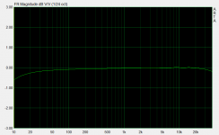
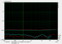
The frequency response and distortion, measured with ARTA and STEPS respectively, are attached. Distortion levels are at or below 0.001% and flat across the audio band. Frequency response extends down to DC - the rolloff in the FR plot is probably due to the fact that I only used 500msec of the impulse response. There is no DC blocking cap. The board was intended to be used with the miniDSP, which should have no DC offset errors. The LME49720 op-amp that I am using should also have very low DC offset, and I measured 0.25mV at the circuit output with the input shorted. So the performance looks pretty good, and is an order of magnitude better than what I normally associate with the miniDSP itself.
I did find one odd thing - the negative rail is not at the right voltage, so I will have to look into that a little more to see what is causing the issue.
Attachments
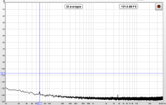
FWIW the spectrum and distortion levels of the board are shown in the attachment below. Not sure why there is a spurious peak at 20kHz, otherwise looks similar to the previous measurements. Mains (60Hz) is 115dB down and other noise/garbage is pretty low in level as well.
Attachments
I managed to track down the issue with the negative rail. The problem was that the negative rail voltage was sitting at about -9.9Vdc when it should have been around -15Vdc. I replaced the regulator IC but this did not have an effect. I then checked and replaced the two resistors that set the output voltage - I thought maybe that the reg needed to source more current to work better, but in that case the voltage should have been more negative but instead it was more positive. The voltage was still not right... After a little more time I discovered in my schematic that I designed the board with the capacitor connected to the adjust pin backwards (polarity reversed) and it was passing a small amount of current. Oops. This still allowed the reg to function but threw off the voltage setting. I removed the cap and installed a new one with the correct polarity orientation. Now the rail is sitting just where it should be, -15V (to within the voltage regulation of the LM337 at least).
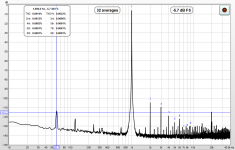
I re-measured the distortion levels and frequency response. These look the same as before, e.g. good. I also made a spectrum measurement. The mains pickup was slightly higher and that odd 20kHz blip was still there and bothering me. I then shorted the input and remeasured the spectrum and the 20kHz peak, as well as all of the mains related peaks, disappeared (see attachment) leaving only a very low level noise floor (of my measurement system). So all of those peaks are being picked up by my DIY twisted pair, non shielded interconnects and are NOT present in or being picked up by the circuit/PCB itself. That's great news. I should probably get a better measurement set up put together, but I am barely up and running at this point after my move.
-Charlie
Attachments
I forgot to mention the gain used for the board described in the last couple of posts. I built up this board to have 12.5dB of gain. When connected to the 2x4 (it is spec's at 0.9V max output but performance is better at 0.5Vrms) you can achieve almost 4Vrms at the output of the gain board with the full 0.9V output of the miniDSP, and even at 0.5Vrms output you will get over 2Vrms out of the gain stage. This is enough to drive most any consumer amplifier well into clipping. That's not the intended purpose - what you are getting is the ability to boost the average output level of high-headroom tracks without having to risk hitting digital 0dB inside the miniDSP.
The gain stage amplifier is in the non-inverting configuration so the output and input are always in phase. Any gain greater than 0dB can be achieved - it's up to the builder. Something between 10dB and 20dB is probably the sweet spot since too much gain will also raise up the noise floor of the miniDSP. Even with more than 12dB of gain the performance of the board is excellent and noise very low.
The gain stage amplifier is in the non-inverting configuration so the output and input are always in phase. Any gain greater than 0dB can be achieved - it's up to the builder. Something between 10dB and 20dB is probably the sweet spot since too much gain will also raise up the noise floor of the miniDSP. Even with more than 12dB of gain the performance of the board is excellent and noise very low.
Still watching the progress of this. I'm envisioning a case with two of these and my two MiniDSP units powered by (I'm not 100% sure yet). I'm most excited to be able to set the MiniDSP gains down, so that no amount of EQ fussing will overdrive the MiniDSP, while still having a DB or two of headroom, so I don't have to ride the edge of linearity to flick the last level indicator on my subwoofer amplifiers.
Once the cost is figured up concretely, I'll try to budget a couple of these once you're all finished. I'm not in any kind of hurry, it's going to be some tinkering to get all my gains set properly again...plus I have a sneaking suspicion that there's an amplifier sitting under the christmas tree currently, so it's going to be at least January before I mess with anything in the rack.
Once the cost is figured up concretely, I'll try to budget a couple of these once you're all finished. I'm not in any kind of hurry, it's going to be some tinkering to get all my gains set properly again...plus I have a sneaking suspicion that there's an amplifier sitting under the christmas tree currently, so it's going to be at least January before I mess with anything in the rack.
I will figure out pricing. I can probably offer a PCB+parts kit or just the PCB. It's all thru-hole parts. I will have an option for PS only, PS+gain stage, and gain stage only. For instance if you were using two boards (next to each other) you only need use the PS on one board and can just bridge the supplies using the DC power ports.
I should probably start a new thread in the Vendor's Bazaar forum so as not to offend the mods.
I should probably start a new thread in the Vendor's Bazaar forum so as not to offend the mods.
I to put together a BOM for the project using Mouser part numbers and have calculated the parts cost. In the (low) quantities that are needed you are paying through the nose for the parts! A group buy might be in order... I'll try to figure out some other lower cost solutions as well. If you have suggestions about how people can get lower cost parts for this project, please contact me.
The fully built out board with power supply (using the high Mouser prices!) comes to just under $50. This includes the transformer(s) - everything except the cables to connect it to other components. If you already have an appropriate power supply or want to power additional board(s) from the PS on the first board, the parts for the built board without power supply runs about $27. PCB only would be $15. All of the above come with the BOM and build instructions.
Note the above is not an advertisement, just info for those who were asking. If you want one of these urgently you can contact me, otherwise look for a thread in the Vendor's Bazaar section soon.
The board is designed for thru-hole components. You will need to have experience with soldering, but there is not anything difficult to the assembly procedure.
- Status
- This old topic is closed. If you want to reopen this topic, contact a moderator using the "Report Post" button.