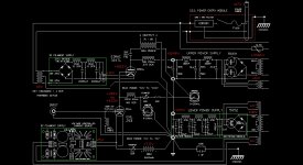
It's a CLCLC..... 20000uf / 10mH / 20000uf / 10mH / 20000uf.
parallel to each cap is a 470K ohm (or will be when built) bleeder resistor.
Jeff
parallel to each cap is a 470K ohm (or will be when built) bleeder resistor.
Jeff
good find! what a deal! you need a cap before them.
Like you mentioned before.. sometimes PSUD doesn't match the real world, but when I modeled with PSUD I had to make some assumptions... The Hammond 167 filament tranny is rated at 18v, but I had to assume a 20V unloaded value for PSUD, as most tranny's I've tested always measure the unloaded voltage from 10% to 20% higher than the published RMS rating. So Assuming I have 20.5 volts realworld unloaded ( and PSUD says to use unloaded voltages in their model), if I had just a LCLC, the output voltage was a bit too high. so changing from a choke load to a capacitor load using the SS rectifier, I actually got a voltage drop in the PSUD model to where the output voltage needed to be. Also I had a couple of recomendations from a couple of 304 amp builders that they uses a CLCLC filter for their supplies.
The chokes have a 12.5 amp rating and that is what the filaments in series require. The tranny is able to put out and is rated at the 5v up to 15 amps, of which only 12.5 amps will be drawn from it from the filaments, so the chokes should be fine as they aren't going to be used at the 15A.
Once I get the actual physical transformer in my hand I can take actual unloaded voltage measurement and plug them in the model. Also I have some bigazz 300watt .8 ohm load resistors that I'll use to do a bread board model of the supply to dial in the voltage.
The heaters static resistance in series is .8 ohms.... with 5 volts @ 12.5 amps, thats 125 watts... So the schematic is still "fluid" untill parts are in hand, meaurements are taken and bread board mockups are finished to see actual occurances.
Jeff
Last edited:
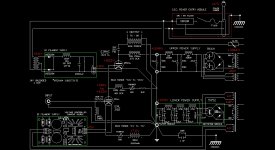
Another refinement to the 304 DC heater supply. Took off the amperage rating of the power transformer so as not to confuse it's max rating with it's actual output. I also noted the approximate unloaded measured voltage and its DCR.
I removed the first C, thereby changing it to an LCLC filter. I also inserted two .5 ohm resistor on each leg of the transformer secondary before the rectifier to increase the effective DCR of the tranny from .1R to 1.1R. Using PSUD, this lowers the voltage at the output of the filter to the 10 volts needed for the filament. After the breadboard is built, I will take actual measurements and trim the values to get the real world numbers needed.
JD
Attachments
I removed the first C, thereby changing it to an LCLC filter. I also inserted two .5 ohm resistor on each leg of the transformer secondary before the rectifier to increase the effective DCR of the tranny from .1R to 1.1R. Using PSUD, this lowers the voltage at the output of the filter to the 10 volts needed for the filament. After the breadboard is built, I will take actual measurements and trim the values to get the real world numbers needed.
JD
Jeff, a couple of notes
That 10mH/12.5A choke will not work in that circuit at the input ... it should be gapped for 15A as a minimum as it will pass the DC for the filament and filter the AC. Used that way it will buzz and the filter will not work as L input but (kind) like C-input.
A 0.5 ohm resistor in the filter will wast 80W of heat, you are using two of them which is 160W and that is for one channel only. This is not going to work, you will melt everything.
For a 304TL heater you really need to have a multitapped power transformer to hit the 10V at the filaments with a reasonable precision (+/- 5%). That is a trial and error process and you really want to tune it on the real thing.
There are no workarounds. You may still use a SMPS.
Gianluca
Thanks..
If I were to change the first choke to say.. 15mH / 16A (found one off the shelf @ 18lbs weight), could the second choke still be the 10mH / 12.5A? as the second choke does improve the voltage (on paper).
Bumping up th wattage on the R's isn't really an issue. I was just taking the RMS current at the transformer (as the value PSUD was giving) and using that to equate the wattage with ohms law. I arrived at 12.5 watts.
RMS current was about 5 amps, resistor is .5R so P=Isquared X R = 12.5 watts. I doubled to 25 watts for good measure as the resistor was not the final after rectifier DC load but a "pass -thru" of AC
The SMPS is starting to look better again
JD
Jeff, a couple of notes
That 10mH/12.5A choke will not work in that circuit at the input ... it should be gapped for 15A as a minimum as it will pass the DC for the filament and filter the AC. Used that way it will buzz and the filter will not work as L input but (kind) like C-input.
A 0.5 ohm resistor in the filter will wast 80W of heat, you are using two of them which is 160W and that is for one channel only. This is not going to work, you will melt everything.
For a 304TL heater you really need to have a multitapped power transformer to hit the 10V at the filaments with a reasonable precision (+/- 5%). That is a trial and error process and you really want to tune it on the real thing.
There are no workarounds. You may still use a SMPS.
Gianluca
A 0.5 ohm resistor in the filter will wast 80W of heat, you are using two of them which is 160W and that is for one channel only. This is not going to work, you will melt everything.
Gianluca
Then consider that 12.5A of current through 1 ohm will drop 12.5V leaving you with an 18V transformer that if it were to deliver 12.5A of current will only supply your bridge with 5.5V.
This really isn't that hard.
18V * .9 = 16.2V
drop 2.8V for the bridge = 13.4
12.5A through .22 ohms drops another 2.75V = 10.65V
If the DCR's of the chokes are rated at 20C when they heat they might go up a bit. You will also lose a bit of voltage in the wiring. In any case if you do find you need to drop the remaining .65V you need 50 milli-ohms.
If it were me and I wanted to lose a fraction of a volt i'd put an appropriately sized thermistor on the primary.
dave
Thanks..
If I were to change the first choke to say.. 15mH / 16A (found one off the shelf @ 18lbs weight), could the second choke still be the 10mH / 12.5A? as the second choke does improve the voltage (on paper).
Bumping up th wattage on the R's isn't really an issue. I was just taking the RMS current at the transformer (as the value PSUD was giving) and using that to equate the wattage with ohms law. I arrived at 12.5 watts.
RMS current was about 5 amps, resistor is .5R so P=Isquared X R = 12.5 watts. I doubled to 25 watts for good measure as the resistor was not the final after rectifier DC load but a "pass -thru" of AC
The SMPS is starting to look better again
JD
Here are my comments:
Average current will be the same 12.5A throughout this supply. That has some implications.
The FRED diode bridge is probably dropping ~4 volts at 12.5A average current once it warms up. It will need a big heatsink to dissipate 50 watts or more. I would look at the 1N5828 Schottky diode which will drop < 1 volt in a bridge configuration.
0.5 ohm resistors will dissipate 12.5^2*0.5 ~78 watts each.
I'm skeptical about taking the cathode connection from the transformer CT. That needs to be thought through as to what artifact will appear at that point. A related issue is the low AC impedance of the final filter cap across the filament, which puts it in the signal current loop.
After thinking about this and playing out all of your design ideas, I would go for a well shielded high quality SMPS with the 10-15mH choke in one line, with the opposite side of the filament used for the cathode connection. Alternatively you could get fancy and use 2 chokes and a 10 ohm resistor divider for the cathode connection. The choke on the SMPS output does 2 things; it filters out any noise from the SMPS (could use a RFC also if needed), and it provides a high impedance block to the audio signal current that will appear across the filament. This will additionally allow you to reconsider 5V operation.
The ammeter connections need to be looked at. The top ammeter appears to be shorted across, and the bottom ammeter seems to create a short circuit from driver B+ to ground.
Michael
Thanks guys... lots to consider and reconsider.
Michael...finding a 10mH -15mH choke for 25amps might be too daunting.... size and cost.
The 12.5amps chokes are quite large at it is. A 16amp choke I found for the 10v schem comes in at 18lbs and $135. each. It's about 8"x8"x8".... I can only imagine the 5v25a 15mH choke size!
Seems like the heater supply will be larger than the amp ;^P
ack..... I think I'll just try AC heaters first.
Seems like the heater supply will be larger than the amp ;^P
ack..... I think I'll just try AC heaters first.
it is actually. my amp, not using 304TL's anymore, is a 4 big heavy chassis'. for just 5W per channel.

try AC by all means but wire the filaments for 5V operation.
gianluca
Alright, another have at it.
Changed tranny to 12.6v.(.1DCR), Bridge is Half Wave using Schottky NTE6084 diodes (can't locate 1N5828's) each with a Vf of .55v (in spec sheets) so these are equivelent subs (according to Newark). Changed the choke to 15mH and 16A (found one off the shelf). One big Cap and a bleeder. This should get the voltage to 10. May have to tweak with a little R in the real world... Also wondering If I should shunt (C and/or R ) the diodes... and left the meters off the schematic for now.
JD
Attachments
Last edited:
Dang it... don't tell me... I should have typed full wave not half wave... anyways, you all don't have to tell me about 1/2 vs full and V out...
I'm going to change the schemo back to full wave..... next version ..... need to get full voltage from the secondaries....still using the 1N5828 cuz they have little drop.
Arghh... time to go back and hit some more books.
JD
I'm going to change the schemo back to full wave..... next version ..... need to get full voltage from the secondaries....still using the 1N5828 cuz they have little drop.
Arghh... time to go back and hit some more books.
JD
12.6V *.9= 11.34 choke input
-.55*4=9.14 rectifier drop
- 12.5*.08=8.14 choke DCR
I'd be surprised if you got more than a 8V out of that filter. You could toss in an input cap to get the voltage up to what is needed but your original filter with 18V should be really close to spot on. Why don't you just clip lead the thing up and see... with jumper cables of course
dave
I'm going to scrap the linear supply idea as I can't find a transformer that will both let the 304 have the current it requires at the voltage it requires. Just cant fine one off the shelf that will work after doing the calcs, either the right voltage, but not enough current, or the right current but way to much voltage, trying either bridge or full wave configurations in the calcs.
So I'm going back to the SMPS idea with a choke.
I have accsess to a 12v 12.5A supply. It can be adjusted +/- 10%. (13.2v - 10.8v) I'll adjust it down to 11 volts. I found a choke...15mH @ 16A with .08 dcr..at 12.5A that's 1 volt drop, that should give me both the voltage and the current.
So, that's the plan as it stands (if AC doesn't give satisfactory results)
JD
12.6V *.9= 11.34 choke input
-.55*4=9.14 rectifier drop
- 12.5*.08=8.14 choke DCR
I'd be surprised if you got more than a 8V out of that filter. You could toss in an input cap to get the voltage up to what is needed but your original filter with 18V should be really close to spot on. Why don't you just clip lead the thing up and see... with jumper cables of course
dave
Last edited:
(edit)... sorry for the double post... I thought I was editing the original....so I put just a little more info here...
Doing the calcs for current, with that transformer (18V) doesn't have enough for the 304. Its a Hammond 167U18.... 18V@15A, even the 167V18 with 20A doesn't allow for the 12.5A heater requirement after the filter.
With the bridge I get 11.11A (using the 20A trans)..I out=I AC/1.8 with voltage calcs giving 13v. Finding a drop of 3 volts would require the resistance spoke of earlier along with it's acompanying heat. Just a bit too much V.
If I go full wave The voltage suffers...Vdc=Vac/2.2-Vdiode-(dcr of inductor x I dc) which leaves 6.08v but It will have 14A of current. (Idc=Iac x .707)
That would mean an ideal transformer of 27 volts @ 18amps would work with full wave. Can't find that puppy (or close enough).
So I'm going back to the SMPS supply. I have accsess to a 12V 12.5A supply that is adjustable from 10.8v to 13.2 v. I'll adjust it to 11 volts. I have located a choke of 15mH @16A with a .08 dcr which will give a drop of 1 volt.
And I'm at the 10V and 12.5A. So at the end of the day.. I'm there with the right voltage and correct current for the 304 heater.
So that's the plan as it stands if AC proves unacceptable.
JD
12.6V *.9= 11.34 choke input
-.55*4=9.14 rectifier drop
- 12.5*.08=8.14 choke DCR
I'd be surprised if you got more than a 8V out of that filter. You could toss in an input cap to get the voltage up to what is needed but your original filter with 18V should be really close to spot on. Why don't you just clip lead the thing up and see... with jumper cables of course
dave
Last edited:
(edit)... sorry for the double post... I thought I was editing the original....so I put just a little more info here...
Doing the calcs for current, with that transformer (18V) doesn't have enough for the 304. Its a Hammond 167U18.... 18V@15A, even the 167V18 with 20A doesn't allow for the 12.5A heater requirement after the filter.
With the bridge I get 11.11A (using the 20A trans)..I out=I AC/1.8 with voltage calcs giving 13v. Finding a drop of 3 volts would require the resistance spoke of earlier along with it's acompanying heat. Just a bit too much V.
If I go full wave The voltage suffers...Vdc=Vac/2.2-Vdiode-(dcr of inductor x I dc) which leaves 6.08v but It will have 14A of current. (Idc=Iac x .707)
That would mean an ideal transformer of 27 volts @ 18amps would work with full wave. Can't find that puppy (or close enough).
So I'm going back to the SMPS supply. I have accsess to a 12V 12.5A supply that is adjustable from 10.8v to 13.2 v. I'll adjust it to 11 volts. I have located a choke of 15mH @16A with a .08 dcr which will give a drop of 1 volt.
And I'm at the 10V and 12.5A. So at the end of the day.. I'm there with the right voltage and correct current for the 304 heater.
So that's the plan as it stands if AC proves unacceptable.
JD
I think the SMPS is probably a good choice.
I'd say the main drawback with the track you were on is a lot of excess heat.
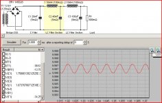
A tractable approach to linear might be with a 12.6V transformer and Schottky bridge with CLCL filter (the final 100uF is just there to fool PSUD2)
Michael
Attachments
I'll need to "back calculate" to find the current the transformer will need so the heaters get 12.5A.
JD
JD
I think the SMPS is probably a good choice.
I'd say the main drawback with the track you were on is a lot of excess heat.
A tractable approach to linear might be with a 12.6V transformer and Schottky bridge with CLCL filter (the final 100uF is just there to fool PSUD2)
Michael
I'll need to "back calculate" to find the current the transformer will need so the heaters get 12.5A. That comes to 22.5 amps or more needed.
using: Iac=Idc/1.8.. for grins I'll see what I can find on the shelf.
ack..... only up to 20 amps from hammond ( 11.11A after the rectifier / filter)
Thanks Michaael, David and Gianluca....
the adventure continues...
JD
using: Iac=Idc/1.8.. for grins I'll see what I can find on the shelf.
ack..... only up to 20 amps from hammond ( 11.11A after the rectifier / filter)
Thanks Michaael, David and Gianluca....
the adventure continues...
JD
I think the SMPS is probably a good choice.
I'd say the main drawback with the track you were on is a lot of excess heat.
A tractable approach to linear might be with a 12.6V transformer and Schottky bridge with CLCL filter (the final 100uF is just there to fool PSUD2)
Michael
Last edited:
- Home
- Amplifiers
- Tubes / Valves
- 304TL based Class A