back to the basics
Anyone who has looked at Eimac's published tube curves for the 304TL, has seen that they are not plotted in the traditional manner for triodes, with plate current VS plate voltage. Maybe I'm making work for myself and this is a completely academic exercise, but is it possible to re-plot this data in the traditional form? Can someone help to get me started. If it can be done, I'll do it and publish the results here.
Anyone who has looked at Eimac's published tube curves for the 304TL, has seen that they are not plotted in the traditional manner for triodes, with plate current VS plate voltage. Maybe I'm making work for myself and this is a completely academic exercise, but is it possible to re-plot this data in the traditional form? Can someone help to get me started. If it can be done, I'll do it and publish the results here.
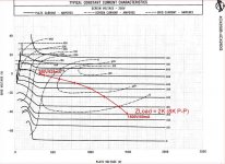
The short answer is “yes”. Often manufacturers of power tubes intended for RF applications show “Constant Current Characteristics” in their data sheets rather than the more familiar “Plate Characteristic” curves. The same data is captured in either depiction. To plot the plate characteristics, keep in mind that each data point involves three linked parameters: Plate voltage, plate current and grid voltage (ignoring grid current for the moment). In other words, for each combination of plate current and plate voltage, there is only one value of grid voltage. And for each combination of plate voltage and grid current, there is only one value of plate current, and so on. Each linked combination of three parameters is plotted as a single point in either type of chart. If you record those points and then re-plot them onto a plate characteristics chart, you can slowly build the familiar looking curves. Knowing that the familiar charts are curves drawn along constant grid voltages, you might start by looking horizontally across the Eimac chart at one value of grid voltage and pick up various pairings of plate current and plate voltage. For example, look at the grid voltage of -50V on the Eimac. That’s an imaginary (undrawn) horizontal line departing from the Y-axis at -50V. At 1000 v, current is about 250mA. There’s your first data point. Then look across and see 1500 volts and 750mA (approximately). You’ll have to interpolate between the lines in many cases. Now plot a grid voltage curve for -50V on your new chart with these data points. With enough points, the curves will begin to reveal themselves. Is all this worth it? I can’t say. I’ve done it before, and it’s tedious.
I will try to explain about the filament(s) again: a 304TL is really just four 75TL's (or two 152TL's) in one bottle. It's not just electrically equivalent to four 75TL's, Eimac literally took the guts of four 75TL's and suspended them around a central support. A 152TL is two 75TL's.
The filaments are brought out in parallel pairs. Two of the pins in the base light up two of the sections in parallel. The other two pins are for the other two sections. Note that a 75TL has a single filament that runs 5V@6.25A while the 152TL brings the filaments out in parallel for 5V@12.5A operation. Maybe we should think of the 304TL as two 152TL's with the filament connections brought out separately.
The bias point of any tube is determined by the difference in voltage between the grid and cathode. In the case of a directly heated tube like this, the filament is the cathode. In order to talk about bias voltage we might take the average of the two ends of the filament. For example, if we heat the filament with 5V DC, ground the negative end, then apply -50V to the grid, we might say the tube is biased at -52.5V.
In the particular case of the 304TL, if we run the filaments in series for 10V operation then two of the sections will be biased at -52.5V and the other two will be biased at -57.5V. That doesn't seem to me like a good way to make use of the four sections.
If you want to heat with AC @10V, then I suppose you could ground the center connection of the series connected filaments. That would put all the sections at equal bias. This trick won't help with DC.
#########
As for the curves in the Eimac data sheet, in principle you could recreate more conventional plate curves from the constant current curves by sampling a bunch of points and plotting them in the familiar way. The problem is that the published curves don't have the resolution you need. You will want to run in the 100 - 300mA range, but the bottom three curves are 0, 250mA, and 500mA. To plot a good set of curves you would need at least a few more constant current curves in there. Go ahead and try....
The other problem is that the data for tubes like this (big class C transmitting tubes) seems to be somewhat unreliable at the operating points we want to run for class A. In other words, even if the constant current curves offered enough resolution, the resulting plate curves that you derived from them would probably be wrong. So much for all of your time spent gazing at plate curves to find the ultimate operating point.
I will offer the same advice I offered before: build the amp with variable B+ and grid supplies (you would want to anyway, even if you had a very specific operating point in mind) then just twist the knobs on the variacs until it sounds right. It's only two knobs. Really just one knob if you limit yourself to running at max plate dissipation as the tubes were designed to be run: try different plate voltages while keeping the bias at whatever it needs to be to keep the plates visibly glowing orange.
Just for kicks, here's a photo of Jeffrey Jackson's 304TL amp:
You can read more about it here
-- Dave
An externally hosted image should be here but it was not working when we last tested it.
The filaments are brought out in parallel pairs. Two of the pins in the base light up two of the sections in parallel. The other two pins are for the other two sections. Note that a 75TL has a single filament that runs 5V@6.25A while the 152TL brings the filaments out in parallel for 5V@12.5A operation. Maybe we should think of the 304TL as two 152TL's with the filament connections brought out separately.
The bias point of any tube is determined by the difference in voltage between the grid and cathode. In the case of a directly heated tube like this, the filament is the cathode. In order to talk about bias voltage we might take the average of the two ends of the filament. For example, if we heat the filament with 5V DC, ground the negative end, then apply -50V to the grid, we might say the tube is biased at -52.5V.
In the particular case of the 304TL, if we run the filaments in series for 10V operation then two of the sections will be biased at -52.5V and the other two will be biased at -57.5V. That doesn't seem to me like a good way to make use of the four sections.
If you want to heat with AC @10V, then I suppose you could ground the center connection of the series connected filaments. That would put all the sections at equal bias. This trick won't help with DC.
#########
As for the curves in the Eimac data sheet, in principle you could recreate more conventional plate curves from the constant current curves by sampling a bunch of points and plotting them in the familiar way. The problem is that the published curves don't have the resolution you need. You will want to run in the 100 - 300mA range, but the bottom three curves are 0, 250mA, and 500mA. To plot a good set of curves you would need at least a few more constant current curves in there. Go ahead and try....
The other problem is that the data for tubes like this (big class C transmitting tubes) seems to be somewhat unreliable at the operating points we want to run for class A. In other words, even if the constant current curves offered enough resolution, the resulting plate curves that you derived from them would probably be wrong. So much for all of your time spent gazing at plate curves to find the ultimate operating point.
I will offer the same advice I offered before: build the amp with variable B+ and grid supplies (you would want to anyway, even if you had a very specific operating point in mind) then just twist the knobs on the variacs until it sounds right. It's only two knobs. Really just one knob if you limit yourself to running at max plate dissipation as the tubes were designed to be run: try different plate voltages while keeping the bias at whatever it needs to be to keep the plates visibly glowing orange.
Just for kicks, here's a photo of Jeffrey Jackson's 304TL amp:
An externally hosted image should be here but it was not working when we last tested it.
You can read more about it here
-- Dave
The data sheet shows two isolated, completely independent filaments. I was thinking along the lines of a centre-tapped 5 volt transformer to each filament, each filament transformer's centre tap tied to ground.
Any idea on that? It seems to me it could work.
Ciao
Gianluca
[I]PT's for filter chokes[/I]
Considering all of the transformers I have accumulated over the years, I was wondering if these could be used as filter chokes in B+ supplies. It would even be possible to apply DC to an auxiliary winding to control saturation and thus adjust effective inductance.
I would be surprised if this has not been attempted in the past.
Any comments?
Thanks in advance.
Frank
Power and filiament Transformers
I have several Power supplies that came out of units that used 304TL. The DC current on them are aprox. 600 ma and the voltage is in the area of 1500 Volts. They also contain a filament transformer for the 304TL. I am on the road right now but I will give more specs. and picts. if anyone is interested in them.
Don
Re: Power and filiament Transformers
I have a project needing 1500V B+ and either a single 1A or dual
500mA supplies. I haven't sourced many parts yet, and some things
like chokes and caps seem a little uncommon. I may be interested
but I'm using 4X150s, not 304TLs so won't need the filament trans.
Michael
rrcomand said:I have several Power supplies that came out of units that used 304TL. The DC current on them are aprox. 600 ma and the voltage is in the area of 1500 Volts. They also contain a filament transformer for the 304TL. I am on the road right now but I will give more specs. and picts. if anyone is interested in them.
Don
I have a project needing 1500V B+ and either a single 1A or dual
500mA supplies. I haven't sourced many parts yet, and some things
like chokes and caps seem a little uncommon. I may be interested
but I'm using 4X150s, not 304TLs so won't need the filament trans.
Michael
nhuwar said:1 amp why so much b+?
How much power are you looking to get out of this amp?
Nick
Well, I have this pair of OPTs that weigh 25 lbs... each. They're
potted for HV and have 8K primary impedance plate-plate. They
are supposed to be good for 300W.
Then I have this idea for a scalable class AB, 2 stage amp using beam
tubes, and the 4X150/4CX250 are a good fit in the 1200-1500V
B+ range for my OPTs.
It's all really limited by the power supply. One promising load line is
440mA for 2 tubes dissipating 300W and delivering about 360W into
8000 ohms plate-plate. Idle is 40-50mA, or 120-150W per channel.
It can be scaled back to lower voltage and operated at 16K Zpri
for other op points and lower idle dissipation. so 1500V/440mA is
the edge of the envelope. One nice feature of these tubes is low
filament power and no need to run the plate red hot, so the amp
can be scaled back to lower power levels efficiently.
It's all on paper still and awaiting a few more lower power experiments
Michael
PS 1A of B+ is for a stereo amp, 440mA per side at max output
Well I might have a potted plate transformer that will work for that. I will have to check the current rating but I think it's close to an amp. It puts out 1500 vac.
Let me know if you are interested. It's a nice one that I had bought for an 833 amp that never materialized.
Nick
Let me know if you are interested. It's a nice one that I had bought for an 833 amp that never materialized.
Nick
304TL Power Supply
Hi
I'd be interested in what your power supplies are like.
Hi
I'd be interested in what your power supplies are like.
I have several Power supplies that came out of units that used 304TL. The DC current on them are aprox. 600 ma and the voltage is in the area of 1500 Volts. They also contain a filament transformer for the 304TL. I am on the road right now but I will give more specs. and picts. if anyone is interested in them.
Don
back to the basics
Anyone who has looked at Eimac's published tube curves for the 304TL, has seen that they are not plotted in the traditional manner for triodes, with plate current VS plate voltage. Maybe I'm making work for myself and this is a completely academic exercise, but is it possible to re-plot this data in the traditional form? Can someone help to get me started. If it can be done, I'll do it and publish the results here.
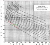
Just plot the load line on the constant current chart. It won't be a straight line, but then neither is a real life load line. You can still use it in the same way as a load line plotted on a plate characteristics chart. I calculate the V/I intersections based on the load impedance starting at the idle point as below:
Attachments
Ok that plots not supposed to be for a 304tl is it? I see its a 4cx250. Just wanted to get a little clarification.
It is a 4cx250, which I used to illustrate the process because I already had it worked out. I haven't worked out a load line for the 304tl yet but for class A you would do the same process starting at the quiescent point and work the slobe both directions above and below.
Cheers,
Michael
PS the 1500V transformer sounds useful but for a 1200V L-input or 1800V C-input but it might be hard to get 1400-1500V DC out.
Last edited:
Hi Michael,
Ok Just wanted to be sure. Well my whole plan was using a tube regulator but I don't know if thats going to happen anytime soon.
The 4cx250 is very interesting though, I might play around with that one,
The 3cx300 would be a good series regulator; they seem to go for $50-$80 US when you can find them. Maybe a 4cx250 with plate feedback would work, and have an equivalent Ri of a couple hundred ohms. Try *that* with a triode.
The actual tube I am playing with is the 4x150 and variants, which has the same characteristic curves as the 4cx250, main differences being glass instead of ceramic (you can actually see the filament glow through the little insulator ring and out the bottom), and lower RF power ratings than the 4cx250 but for audio who cares. They can sometimes be found cheaper than 4CX250s, which are used in a lot of RF amps in service today.
Last edited:
Hey Michael! funny meeting you here!
Anyways I was looking for 304TL info and came across this thread.
I've got a couple of nos Eimacs on the way and just starting down the same road as the originator of this thread.
I sent him a p.m. to ask for his state of project as it's been a while since the thread was started.
My goals... SE amp. I don't necesarily have to run the tube at max plate so having ALL the watts is not really an issue. My comfort level with high voltage is growing as my last amp, with Michael's help ( a 2 stage direct connected 437a / 300b amp with stacked suppplies.. about 800 volts from top to bottom).
So how goes it??
Jeff Davison
Hey Michael! funny meeting you here!
Anyways I was looking for 304TL info and came across this thread.
I've got a couple of nos Eimacs on the way and just starting down the same road as the originator of this thread.
I sent him a p.m. to ask for his state of project as it's been a while since the thread was started.
My goals... SE amp. I don't necesarily have to run the tube at max plate so having ALL the watts is not really an issue. My comfort level with high voltage is growing as my last amp, with Michael's help ( a 2 stage direct connected 437a / 300b amp with stacked suppplies.. about 800 volts from top to bottom).
So how goes it??
Jeff Davison
Hi Jeff,
Sorry, I was out of town for 2 weeks with no internet access. Kind of nice actually...
It sounds like you picked an interesting project with some serious industrial design opportunities.
I would first look at what your loudspeaker load is and what damping factor you like, plus power level. Then think about an output transformer.
Here is an example class A1 starting point of 35-40W Po using Zpri of 5K ohms. The plate resistance of the 304tl at this point is about 1500 ohms. This will give you a DF of about 2.5-3 depending on DCR of the OPT.
You will need enough plate dissipation to get a red color for good tube life. The op point below is about 150W Pd, which may get you there. It could be scaled up in voltage if needed.
The drive requirement is similar to a 300B in terms of voltage and driver load capacitance is about 75pF; about 1.5X that of a 300B. There may be some grid current as you approach 0V at peak plate current. Rgrid circuit in non-grid current mode is 250K ohms maximum.
I think a 2 stage topology is perfectly reasonable (I think I have seen a 15E driving a 304TL in one of Jeffrey Jackson's amps). I think you will want a mu of about 40, so a 3C24 may be a little low. Maybe a 25T or 35T would give you enough gain. I have had great results using a stacked mu-follower to drive grid current on Eimac tubes. See:
http://www.diyaudio.com/forums/tubes-valves/144767-class-a2-direct-mosfet-coupled-se.html
Any progress lately?
Michael
Attachments
I heard a 250TH SE amp mono block outfit
75W per ch.
it is more than enough power i was thinking...
but somehow i found that the OT
is from vital importance for this type tube design?
it has to be very "big", in henrys, core, insulation
probably?
this one was not good enough, lacking bass
mids are little sharp...
75W per ch.
it is more than enough power i was thinking...
but somehow i found that the OT
is from vital importance for this type tube design?
it has to be very "big", in henrys, core, insulation
probably?
this one was not good enough, lacking bass
mids are little sharp...
- Home
- Amplifiers
- Tubes / Valves
- 304TL based Class A