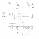
Revised XO component order. It was quite a task trying to get the R values correct but I think managed to match the XSim values exactly now ")
2 × LL60-130 - Mundorf M-Coil LL60 1mH inductor LL60-130
2 × L50-050 - Mundorf M-Coil L50 0.22mH inductor L50-050
2 × BL125-190 - Mundorf M-Coil BL125 2.7mH inductor BL125-190
2 × BL100-070 - Mundorf M-Coil BL100 0.33mH inductor BL100-070
2 × BS100-110 - Mundorf M-Coil Feron-Core BS100 4.7mH BS100-110
2 × L71-250 - Mundorf M-Coil L71 6.8mH inductor L71-250
12 × MR10-110 - 1R Mundorf M-Resist 10W Metal Oxide Resistor MR10-110
4 × MR10-130 - 1R5 Mundorf M-Resist 10W Metal Oxide Resistor 1.5R MR10-130
2 × MR10-160 - 2R7 Mundorf M-Resist 10W Metal Oxide Resistor 2.7R MR10-160
4 × MR10-170 - 3R3 Mundorf M-Resist 10W Metal Oxide Resistor 3.3R MR10-170
2 × MR10-030 - 0R22 Mundorf M-Resist 10W Metal Oxide Resistor 0.22R MR10-030
2 × MR10-230 - 10R Mundorf M-Resist 10W Metal Oxide Resistor MR10-230
2 × MR10-240 - 12R Mundorf M-Resist 10W Metal Oxide Resistor MR10-240
2 × MR10-180 - 3R9 Mundorf M-Resist 10W Metal Oxide Resistor 3.9R MR10-180
4 × EVO-220: 8.2uF 450V Mundorf Mcap EVO Capacitor EVO-220
2 × EVO-250: 15uF 450V Mundorf Mcap EVO Capacitor EVO-250
2 × EVO-330: 100uF 350V Mundorf Mcap EVO Capacitor EVO-330
2 × EVO-230: 10uF 450V Mundorf Mcap EVO Capacitor EVO-230
4 × EVO-270: 22uF 450V Mundorf Mcap EVO Capacitor EVO-270
2 × NKX-070 - 330uF 450V Nichicon KX type, LKX2W331MESB45 NKX-070
2 × NKX-020 - 100uF 450V Nichicon KX type, LKX2W101MESY40 NKX-020
2 × EVO-030: 0.15uF 450V Mundorf Mcap EVO Capacitor EVO-030
Inductor build specs
Mundorf M-Coil L50 0.22mH inductor : will be 0.2mH
Mundorf M-Coil BL125 2.7mH inductor : will bee 2.4mH
Mundorf M-Coil BL100 0.33mH inductor: will be 3.0mH
Mundorf M-Coil Feron-Core BS100 4.7mH : will be 4.5mH
That's around £220 per XO!
spark, I apologize if I didn't explain this well enough before. Really the only inductor whose resistance is absolutely important is L1, the 4.5mH on the woofer. Keep it at about .3ohm. But you are more or less free to choose the resistance value of every other coil. Which means that every air core inductor could probably use the thinner and cheaper 20AWG wire.
The reason for this is that resistance sums when in series and every coil except L1 and L3 also has a true resistor in series with it (see below). So for eg, on the tweeter parallel leg, the R values of L4 and R9 should add to about 2.5ohm. So if your coil is .5ohm then you need 2ohm for the resistor. If you get a coil with 1ohm resistance, then you only need 1.5ohm for the true resistor.
In the woofer circuit, L2 and R1 should add to about 6ohm. In the mid LCR, L6 and R10 should add to about 13ohm.
L3 works well with resistance anywhere between .5 and 1ohm. The higher R value will be less expensive.
Here's something else to know. As the values become larger and larger, you have a little more wiggle room to play with. In that mid LCR circuit, 13ohm, 13.3ohm or 12.7ohm aren't going to be very different. In the woofer circuit, if I was changing C1, I would be doing it in 10uF increments. But in the tweeter circuit, both C5 and L4 are small enough that small changes in value make a fairly significant change to both the FR and the phase response. This is the case with C8 as well. I'd say .11, .12 and .13uF are acceptable but .15uF is going a little too far. That component is targeting a very specific resonant frequency at about 6.8kHz and so needs to be quite accurate.
You have the XSim program. Make a copy and then start re-doing it with all the exact component values that you are thinking of ordering. I think that should really help you to see how everything works together.
Hope that helps.
Attachments
spark, I apologize if I didn't explain this well enough before. Really the only inductor whose resistance is absolutely important is L1, the 4.5mH on the woofer. Keep it at about .3ohm. But you are more or less free to choose the resistance value of every other coil. Which means that every air core inductor could probably use the thinner and cheaper 20AWG wire.
The reason for this is that resistance sums when in series and every coil except L1 and L3 also has a true resistor in series with it (see below). So for eg, on the tweeter parallel leg, the R values of L4 and R9 should add to about 2.5ohm. So if your coil is .5ohm then you need 2ohm for the resistor. If you get a coil with 1ohm resistance, then you only need 1.5ohm for the true resistor.
In the woofer circuit, L2 and R1 should add to about 6ohm. In the mid LCR, L6 and R10 should add to about 13ohm.
L3 works well with resistance anywhere between .5 and 1ohm. The higher R value will be less expensive.
Here's something else to know. As the values become larger and larger, you have a little more wiggle room to play with. In that mid LCR circuit, 13ohm, 13.3ohm or 12.7ohm aren't going to be very different. In the woofer circuit, if I was changing C1, I would be doing it in 10uF increments. But in the tweeter circuit, both C5 and L4 are small enough that small changes in value make a fairly significant change to both the FR and the phase response. This is the case with C8 as well. I'd say .11, .12 and .13uF are acceptable but .15uF is going a little too far. That component is targeting a very specific resonant frequency at about 6.8kHz and so needs to be quite accurate.
You have the XSim program. Make a copy and then start re-doing it with all the exact component values that you are thinking of ordering. I think that should really help you to see how everything works together.
Hope that helps.
Hi jReave, The order been placed already... My keenness to get cracking has probably cost me more than necessary. Other than the C8 do you think the components will be ok?
Ok great. I'll get a better match for C8 sorted and i'm reasonably confident with the resistance. If its lower than required, I can always add a resister to compensate. If its higher I'm in trouble
To get exactly 0.12uF i'll need to combine 3 caps.
1 x 0.1uF 650V Mundorf Mcap EVO Capacitor
2 x 0.01uF 650V Mundorf Mcap EVO Capacitor
Do you think that will be ok for C8?
To get exactly 0.12uF i'll need to combine 3 caps.
1 x 0.1uF 650V Mundorf Mcap EVO Capacitor
2 x 0.01uF 650V Mundorf Mcap EVO Capacitor
Do you think that will be ok for C8?
Ok great. I'll get a better match for C8 sorted and i'm reasonably confident with the resistance. If its lower than required, I can always add a resister to compensate. If its higher I'm in trouble
Not really. If it's higher, just reduce the true resistor value. I think you probably have enough resistors to make that work.
To get exactly 0.12uF i'll need to combine 3 caps.
1 x 0.1uF 650V Mundorf Mcap EVO Capacitor
2 x 0.01uF 650V Mundorf Mcap EVO Capacitor
Do you think that will be ok for C8?
That will work perfectly.

I was trying to tell you.
haha, yes but.... i kinda got carried away
I've mocked up a very rough layout of the components. There's plenty of tweak space for the capacitors and resistors (not shown on image). My main objective and concern is the inductor placement. What do you think of the latter?
Attachments
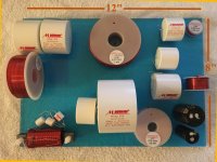
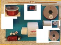
Looks good except perhaps for the left side where the iron core and the 1 above it are coiled in the same orientation. It's messy but I would probably do something like the attached - all the big coils flat in the corners and then the 2 other small ones in between. Locations might depend on keeping the 2 mid coils and the 2 woofer coils close together for easier and shorter wiring if you know what I mean.
Attachments
Thanks for the advice jReave. Here's my new proposed layout. I think it takes onboard your comments and also uses the guide Placement of coils in crossover networks
Basically all of my inductors are less than 20cm apart, so I think having a few of them upright should give really good result..? if we ignore the practicalities of fixing them to the perspex board
I plan on using very thick wire so hopefully there wont be no transmission losses worth worrying about over the longer lengths needed in a more spread out design?
Attachments
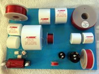
To be nit-picky, the coil in the middle of the board is slightly askance to the 4 corner coils but I think it will be fine.
It's all good to be using large gauge wire but don't forget that the signal is going through much longer lengths of thinish wire in all of those big inductors. Or in other words, I somehow doubt that you'll hear a difference between thick or thin wire in your xo board but hey, some people would probably claim to, and truth be told, I'd probably do it too just for my own peace of mind.
Zip ties and/or lots of hot glue or silicone caulking or strong industrial glue are your friends on the xo board.
XO built measurements taken
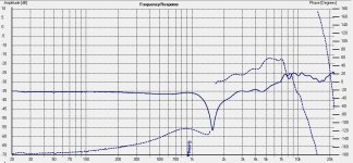
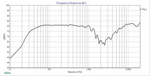
Seeing something very wrong with the mid and the tweeter seems too high. Bizarrely when I play music, there too much bass, the mid is a little weak and the tweeter seems quiet.
Here's the measurements (Image 1). Taken at 27" Listening height. Any ideas?
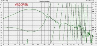
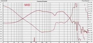
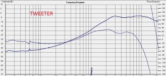
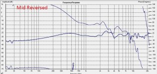
Also here (images 2-4) are the individual NF driver measurements. To take these I disconnected the individual drivers from the XO.
NB: The dotted line is phase
measurements taken Seeing something very wrong with the mid and the tweeter seems too high. Bizarrely when I play music, there too much bass, the mid is a little weak and the tweeter seems quiet.
Here's the measurements (Image 1). Taken at 27" Listening height. Any ideas?
Also here (images 2-4) are the individual NF driver measurements. To take these I disconnected the individual drivers from the XO.
NB: The dotted line is phase
Attachments
Last edited:
Well, let's see if we can't fix you up.
My 1st thought is the same as the previous post - did you wire up the mid with reversed polarity? Tweeter and woofer are wired normally but the mid should be reversed.
Give that a shot. Fingers crossed it's something that simple.
It's also possible that I gave the speaker a little too much baffle step compensation for your room so that the bass may be a little too forward, but let's check out that your wiring and xo implementation is all kosher first before we go and start playing with any xo values.
Actually, if your 1st graph is a measurement of the whole speaker, it may just be your tweeter that's wired wrong. Attached first is what I get when the woofer is wired normally and both the mid and the tweeter polarity are reversed. Pretty similar to what you measured (2nd image), albeit you are showing a narrower null.
Attachments

@jReave @USRFobiwan
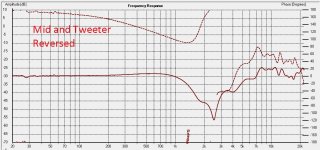
Ok great. Reversing the polarity on the Mid has definitely improved the FR. I also tried reversing the tweeter whilst the mid was reversed.. that gave bad results.
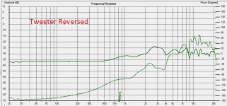
Lastly I tried just reversing the tweeter. That's an interesting FR now
Here are the screen grabs of the FR I've just made.
Ok great. Reversing the polarity on the Mid has definitely improved the FR. I also tried reversing the tweeter whilst the mid was reversed.. that gave bad results.
Lastly I tried just reversing the tweeter. That's an interesting FR now
Here are the screen grabs of the FR I've just made.
Attachments
- Status
- This old topic is closed. If you want to reopen this topic, contact a moderator using the "Report Post" button.
- Home
- Loudspeakers
- Multi-Way
- 3-Way Build Project - Woofer help