Haha, yes i'm getting pretty good at it now. Can knock them out in around 15 mins ")
I'll be leaving the Mid open.. schoolboy error!
If you have the files for XSIM, it would be great to have a go at the XO.
I'm thinking of buying the Caps, Inductors and Resisters from here
Caps
Mundorf MCap Supreme Capacitors | Hifi Collective
Inductors
Mundorf Air-core coils M-Coil, L, BL & VL range | Hifi Collective
Resisters
Mundorf M-Resist Supreme 20 W | Hifi Collective
Your drivers can certainly benefit from high quality xo components but once you start adding up the price tag for all the items you are likely to need, you are probably going to want to reconsider some of those choices.
There will be some values in particular where I'm going to recommend an iron core inductor and a cheaper probably non polarized capacitor. Most suitable to the high end would likely be the components in series with your tweeter and mid.
But, let's find a xo that works first.
There will be some values in particular where I'm going to recommend an iron core inductor and a cheaper probably non polarized capacitor. Most suitable to the high end would likely be the components in series with your tweeter and mid.
But, let's find a xo that works first.
Hey spark,
I'm not clear what you want to do next - do you want to have a go at designing the xo or would you like an early xmas present and I'll post what I've come up with?
Hi jReave (aka
),Early Christmas Present please!
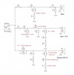
Right then, below is what I came up with.
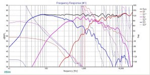
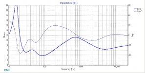
All acoustic slopes are LR2 with xo points at about 500Hz and 2200Hz. Mid polarity is reversed and phase aligns very well through the xo regions. Minimum impedance falls just barely below 4ohm at about 85Hz. That'll be no problem at all. I have targeted a flat response but if that doesn't work for you, you can alter the tweeter and/or the mid levels pretty easily with their series resistors. Both the tweeter and the mid actually needed a fair bit of padding. I used an L-pad on the tweeter and then added a small resistor up front (R8) that makes it easier to adjust. For the mid I liked the response better with series resistance only (R3).
I would suggest steel cored inductors for the woofer circuit. L1 should have as low resistance as possible, more or less, but L2's resistance can be as large as you want.
If you don't know, if an inductor is in series with a resistor, then it's only the total value of the resistance of the inductor plus the value of true resistor that matters. Or in other words, resistance sums in series. So for eg, in the woofer's LCR filter, the total R is about 6ohm so L2's R value is 1ohm. In the mid circuit, L5's resistance can also be large (in the sim I have it at 1ohm ) but if you change it, you also just need to adjust R3 accordingly.
Capacitance on the other hand sums when in parallel which is good to know when you can't find the exact values listed. Again in the woofer LCR, C2 is going to be fine using a less expensive capacitor like a non polarized electrolytic.
Measured responses btw were actually pretty close to the simulations but the acoustic centers of the mid and the woofer were both a bit different than a simple physical measurement would suggest and that meant several changes to the xo from my prior simulation were necessary to get good driver phase alignment. Best was that the tweeter went from 4th order electrical to 2nd order.
Set it up for yourself and play with the values so that you can see what everything does as well as see what variation in components values will still be acceptable.
I'd feel better if I was using measured driver impedance but once you get the xo together, you take another measurement on the tweeter axis of the whole speaker together to see how it corresponds to the sim. And of course, your ears are the final arbiter.
Did I cover everything? Somehow I doubt it. Let me know if you have any questions.
Cheers
All acoustic slopes are LR2 with xo points at about 500Hz and 2200Hz. Mid polarity is reversed and phase aligns very well through the xo regions. Minimum impedance falls just barely below 4ohm at about 85Hz. That'll be no problem at all. I have targeted a flat response but if that doesn't work for you, you can alter the tweeter and/or the mid levels pretty easily with their series resistors. Both the tweeter and the mid actually needed a fair bit of padding. I used an L-pad on the tweeter and then added a small resistor up front (R8) that makes it easier to adjust. For the mid I liked the response better with series resistance only (R3).
I would suggest steel cored inductors for the woofer circuit. L1 should have as low resistance as possible, more or less, but L2's resistance can be as large as you want.
If you don't know, if an inductor is in series with a resistor, then it's only the total value of the resistance of the inductor plus the value of true resistor that matters. Or in other words, resistance sums in series. So for eg, in the woofer's LCR filter, the total R is about 6ohm so L2's R value is 1ohm. In the mid circuit, L5's resistance can also be large (in the sim I have it at 1ohm ) but if you change it, you also just need to adjust R3 accordingly.
Capacitance on the other hand sums when in parallel which is good to know when you can't find the exact values listed. Again in the woofer LCR, C2 is going to be fine using a less expensive capacitor like a non polarized electrolytic.
Measured responses btw were actually pretty close to the simulations but the acoustic centers of the mid and the woofer were both a bit different than a simple physical measurement would suggest and that meant several changes to the xo from my prior simulation were necessary to get good driver phase alignment. Best was that the tweeter went from 4th order electrical to 2nd order.
Set it up for yourself and play with the values so that you can see what everything does as well as see what variation in components values will still be acceptable.
I'd feel better if I was using measured driver impedance but once you get the xo together, you take another measurement on the tweeter axis of the whole speaker together to see how it corresponds to the sim. And of course, your ears are the final arbiter.
Did I cover everything? Somehow I doubt it.
Let me know if you have any questions.Cheers
Attachments
Hi jReave,
Would you mind taking a moment and explain how you arrived at the acoustic offset values? I noticed you had woofer delay at 4.25" and mid at .34". I have been following this thread trying to learn more along the way. Especially, since I will be encountering the same issues in a couple months. Thanks very much in advance!!!
Best Regards and Happy Holidays,
Rich
Would you mind taking a moment and explain how you arrived at the acoustic offset values?
I noticed you had woofer delay at 4.25" and mid at .34". I have been following this thread trying to learn more along the way. Especially, since I will be encountering the same issues in a couple months. Thanks very much in advance!!!Best Regards and Happy Holidays,
Rich
Hey Rich, Merry Xmas to you. Hope you are well.
For acoustic offsets, the important points are here in Jeff Bagby's paper - Finding the relative acoustic offsets. That paper is intended for his PSD xo program and works with the geometry of the drivers and mic setup and the time of flight of the sound waves. In PCD it's essential that you include the driver spacing and the mic distance to arrive at accurate results.
In a nutshell, what you do is set up your mic in a fixed position in front of the tweeter and then take individual measurements of each driver and then each combination of drivers. The way that sound waves combine is dependent on the distance that they have to travel and so what happens is that you end up changing the programs acoustic offset until your measured FR of driver combinations matches with the summation that the program does with the individual driver measurements. It's actually pretty cool when you are changing the z offset and suddenly the 2 FR that were almost nothing alike start to line up perfectly. That's when you have found the driver's acoustic offset in real life.
In XSim, the program doesn't include the particulars of driver and mic locations but the geometry and time of flight still hold true so if you follow through with the same process and simply add time delay to the mid and/or woofer (this time in the positive direction), it will still produce accurate results for this program only.
To perhaps oversimplify, in PCD the program determines the acoustic offset from the front of the baffle (in a negative quantity) and in XSim the program determines the acoustic offset in terms of the difference in the length of the hypotenuse between each driver and the mic. In any case the value of the acoustic offset will always be larger in XSim than in PCD for this reason.
I'm not sure if I'm being perfectly clear because I'm a goodly way through a bottle of wine at this point in the evening so let me know if you have any more questions.
Hi jReave,
Thanks very much for your in-depth reply. Everything you stated makes perfect sense. I have been studying Jeff's paper you referenced and that is the trail I'm going to follow once I'm at the measurement stage. Right now I'm currently in construction mode. I added an additional 8 1/2" to the bottom of these Pioneer CS-77 cabs. This has allowed for about 62 liters net vb for (2) Dayton RS225-8" drivers. Anyways, this has been a fun project. Hopefully, I'll get a hand truck for Xmas. These cabs are going to weight-in around 100+ lbs. once baffles are attached. Yike! I probably won't need to worry about anyone stealing them.
Merry Xmas too You and Enjoy the Holiday Cheer!
Best Regards, Rich
Thanks very much for your in-depth reply. Everything you stated makes perfect sense. I have been studying Jeff's paper you referenced and that is the trail I'm going to follow once I'm at the measurement stage. Right now I'm currently in construction mode. I added an additional 8 1/2" to the bottom of these Pioneer CS-77 cabs. This has allowed for about 62 liters net vb for (2) Dayton RS225-8" drivers. Anyways, this has been a fun project. Hopefully, I'll get a hand truck for Xmas.
These cabs are going to weight-in around 100+ lbs. once baffles are attached. Yike! I probably won't need to worry about anyone stealing them.Merry Xmas too You and Enjoy the Holiday Cheer!
Best Regards, Rich
Hi jReave,
The FR graph looks very nice indeed and a flat response is something I wanted to achieve on this project! I'm impressed and happy with how that's turned out.
Polarity reversing isn't something I was expecting but its not a problem for me to implement. I was actually reading (a few days ago) a little on this subject and how polarity effects phase.
I need to digest all this info and get my head around some of it also
With regards to the inductor.. is the use of iron core purely a cost saving exercise or will iron core in woofer circuit provide better results than air core?
I think you have covered everything (for now) Do you have a copy of the XSim project files, so I can have a play?
Thank you once again.
The FR graph looks very nice indeed and a flat response is something I wanted to achieve on this project! I'm impressed and happy with how that's turned out.
Polarity reversing isn't something I was expecting but its not a problem for me to implement. I was actually reading (a few days ago) a little on this subject and how polarity effects phase.
I need to digest all this info and get my head around some of it also
With regards to the inductor.. is the use of iron core purely a cost saving exercise or will iron core in woofer circuit provide better results than air core?
I think you have covered everything (for now)
Do you have a copy of the XSim project files, so I can have a play?Thank you once again.
I attached a copy of XSim with your 3rd measurements of the drivers and the manufacturers' zma files in post #204 on the previous page. I was thinking it would be good practice for you to put together the components to arrive at my finished results but here's a copy of the finished one below.
The air core is the better inductor to be in series with your woofer but the problem is that you need the inductor's resistance to be low, I would say somewhere around .3ohm. But to achieve high inductance, you also need more and more loops of wire and so to keep resistance low, the wire diameter has to get bigger and bigger too, so now you end up with a very big and a very expensive mass of copper.
However I seem to recall seeing some types of air core inductors out there that do a pretty good job of overcoming this problem but I can't recall now where or which ones they were. If you can find an air core that fits the specs and your budget and available space, then go for it but if you're almost paying more for a single inductor than you did for the driver, I don't think it makes much sense.
Some kind of metal core is still advisable for the woofer parallel inductor as this one isn't quite as important to the SQ.
Attachments
Not sure if you've seen this yet, but it's something to be aware of as soon as you start laying out your xo components.
Coil Placements
Coil Placements
XO Parts ordered with the exception of a couple items I've managed to match the values you provided and where they differ, the impact is only small.. I'm also able to combine a few of them to get an exact match. Delivery time is 18+ days on some of the parts... so its going to be the end of Jan before I assemble everything. I've got a couple of 5mm perspex sheets to mount the components on
Total cost per XO is £165
Here's the parts list... for reference
4 x EVO-220: 8.2uF 450V Mundorf Mcap EVO Capacitor - £23.76 (£5.94 each)
SKU: EVO-220
2 x EVO-250: 15uF 450V Mundorf Mcap EVO Capacitor - £16.22 (£8.11 each)
SKU: EVO-250
2 x EVO-120: 1uF 450V Mundorf Mcap EVO Capacitor - £5.20 (£2.60 each)
SKU: EVO-120
2 x NKX-090 - 470uF 450V Nichicon KX type, LKX2W471MEXC45 - £23.50 (£11.75 each)
SKU: NKX-090
4 x EVO-270: 22uF 450V Mundorf Mcap EVO Capacitor - £50.28 (£12.57 each)
SKU: EVO-270
4 x MR10-030 - 0R22 Mundorf M-Resist 10W Metal Oxide Resistor 0.22R - £3.84 (£0.96 each)
SKU: MR10-030
4 x MR10-170 - 3R3 Mundorf M-Resist 10W Metal Oxide Resistor 3.3R - £3.84 (£0.96 each)
SKU: MR10-170
6 x MR10-130 - 1R5 Mundorf M-Resist 10W Metal Oxide Resistor 1.5R - £5.76 (£0.96 each)
SKU: MR10-130
12 x MR10-110 - 1R Mundorf M-Resist 10W Metal Oxide Resistor - £11.52 (£0.96 each)
SKU: MR10-110
2 x MR10-230 - 10R Mundorf M-Resist 10W Metal Oxide Resistor - £1.92 (£0.96 each)
SKU: MR10-230
2 x MR10-240 - 12R Mundorf M-Resist 10W Metal Oxide Resistor - £1.92 (£0.96 each)
SKU: MR10-240
2 x MR10-180 - 3R9 Mundorf M-Resist 10W Metal Oxide Resistor 3.9R - £1.92 (£0.96 each)
SKU: MR10-180
2 x MR10-190 - 4R7 Mundorf M-Resist 10W Metal Oxide Resistor 4.7R - £1.92 (£0.96 each)
SKU: MR10-190
2 x MR10-050 - 0R33 Mundorf M-Resist 10W Metal Oxide Resistor 0.33R - £1.92 (£0.96 each)
SKU: MR10-050
2 x BL71-050 - Mundorf M-Coil BL71 0.22mH inductor^^ - £9.34 (£4.67 each)
SKU: BL71-050
Please Note:: A non-stock item, allow 18 days for dispatch
2 x BL71-180 - Mundorf M-Coil BL71 2.2mH inductor^^ - £15.34 (£7.67 each)
SKU: BL71-180
Please Note:: A non-stock item, allow 18 days for dispatch
2 x BL71-070 - Mundorf M-Coil BL71 0.33mH inductor - £9.92 (£4.96 each)
SKU: BL71-070
Please Note:: A non-stock item, allow 18 days for dispatch
2 x BL71-130 - Mundorf M-Coil BL71 1mH inductor^^ - £12.12 (£6.06 each)
SKU: BL71-130
Please Note:: A non-stock item, allow 18 days for dispatch
2 x F50-130 - Mundorf M-Coil Ferrite-Core Pin-Core F50 6.8mH - £9.48 (£4.74 each)
SKU: F40-130
Please Note:: A non-stock item, allow 18 days for dispatch
2 x 000-1664 4.3mH Jantzen Air Core Wire coil AWG20, 0.8mm diameter wire - £12.68 (£6.34 each)
SKU: 000-1664
Please Note:: A non-stock item, dispatch after 12th Jan 2017 - Xmas break
2 x (CCTC-020)- 110uF 450Vdc ClarityCap TC Range polypropylene - £47.82 (£23.91 each)
SKU: CCTC-020
with the exception of a couple items I've managed to match the values you provided and where they differ, the impact is only small.. I'm also able to combine a few of them to get an exact match. Delivery time is 18+ days on some of the parts... so its going to be the end of Jan before I assemble everything. I've got a couple of 5mm perspex sheets to mount the components on Total cost per XO is £165
Here's the parts list... for reference
4 x EVO-220: 8.2uF 450V Mundorf Mcap EVO Capacitor - £23.76 (£5.94 each)
SKU: EVO-220
2 x EVO-250: 15uF 450V Mundorf Mcap EVO Capacitor - £16.22 (£8.11 each)
SKU: EVO-250
2 x EVO-120: 1uF 450V Mundorf Mcap EVO Capacitor - £5.20 (£2.60 each)
SKU: EVO-120
2 x NKX-090 - 470uF 450V Nichicon KX type, LKX2W471MEXC45 - £23.50 (£11.75 each)
SKU: NKX-090
4 x EVO-270: 22uF 450V Mundorf Mcap EVO Capacitor - £50.28 (£12.57 each)
SKU: EVO-270
4 x MR10-030 - 0R22 Mundorf M-Resist 10W Metal Oxide Resistor 0.22R - £3.84 (£0.96 each)
SKU: MR10-030
4 x MR10-170 - 3R3 Mundorf M-Resist 10W Metal Oxide Resistor 3.3R - £3.84 (£0.96 each)
SKU: MR10-170
6 x MR10-130 - 1R5 Mundorf M-Resist 10W Metal Oxide Resistor 1.5R - £5.76 (£0.96 each)
SKU: MR10-130
12 x MR10-110 - 1R Mundorf M-Resist 10W Metal Oxide Resistor - £11.52 (£0.96 each)
SKU: MR10-110
2 x MR10-230 - 10R Mundorf M-Resist 10W Metal Oxide Resistor - £1.92 (£0.96 each)
SKU: MR10-230
2 x MR10-240 - 12R Mundorf M-Resist 10W Metal Oxide Resistor - £1.92 (£0.96 each)
SKU: MR10-240
2 x MR10-180 - 3R9 Mundorf M-Resist 10W Metal Oxide Resistor 3.9R - £1.92 (£0.96 each)
SKU: MR10-180
2 x MR10-190 - 4R7 Mundorf M-Resist 10W Metal Oxide Resistor 4.7R - £1.92 (£0.96 each)
SKU: MR10-190
2 x MR10-050 - 0R33 Mundorf M-Resist 10W Metal Oxide Resistor 0.33R - £1.92 (£0.96 each)
SKU: MR10-050
2 x BL71-050 - Mundorf M-Coil BL71 0.22mH inductor^^ - £9.34 (£4.67 each)
SKU: BL71-050
Please Note:: A non-stock item, allow 18 days for dispatch
2 x BL71-180 - Mundorf M-Coil BL71 2.2mH inductor^^ - £15.34 (£7.67 each)
SKU: BL71-180
Please Note:: A non-stock item, allow 18 days for dispatch
2 x BL71-070 - Mundorf M-Coil BL71 0.33mH inductor - £9.92 (£4.96 each)
SKU: BL71-070
Please Note:: A non-stock item, allow 18 days for dispatch
2 x BL71-130 - Mundorf M-Coil BL71 1mH inductor^^ - £12.12 (£6.06 each)
SKU: BL71-130
Please Note:: A non-stock item, allow 18 days for dispatch
2 x F50-130 - Mundorf M-Coil Ferrite-Core Pin-Core F50 6.8mH - £9.48 (£4.74 each)
SKU: F40-130
Please Note:: A non-stock item, allow 18 days for dispatch
2 x 000-1664 4.3mH Jantzen Air Core Wire coil AWG20, 0.8mm diameter wire - £12.68 (£6.34 each)
SKU: 000-1664
Please Note:: A non-stock item, dispatch after 12th Jan 2017 - Xmas break
2 x (CCTC-020)- 110uF 450Vdc ClarityCap TC Range polypropylene - £47.82 (£23.91 each)
SKU: CCTC-020
@jReave i'm going to re-visit the inductor choices. I've discovered that Mundorf make to order, which means I ask for exact specs
Question: Out of the inductors in the XO, which would benefit most from a slightly higher spec? I thinking that upgrading 2 would still be ok budget wise...
Mundorf Air-core Hepta Strand Coils seem like a natural higher spec option.
Question: Out of the inductors in the XO, which would benefit most from a slightly higher spec? I thinking that upgrading 2 would still be ok budget wise...
Mundorf Air-core Hepta Strand Coils seem like a natural higher spec option.
Looks ok from what I can see except for that Jantzen 20AWG inductor. I expect its resistance value is going to be too high - locally, the same animal from Solen has an R value at 1.6ohm. I would be trying to stay down in the .3ohm neighborhood.
Also, I'm not seeing that tiny little .12uF capacitor that goes parallel to the woofer inductor. You may be able to get away without it but your woofer is the only driver of the 3 to have a bad resonance (up around 7kHz) and so I put that capacitor in there to bring it down a little more than the mild 2nd order rolloff does. Up tp you of course, but it's tiny and cheap so I'd say use it.
And I like the way you stocked up on the 1ohm resistors.
@jReave i'm going to re-visit the inductor choices. I've discovered that Mundorf make to order, which means I ask for exact specs
Question: Out of the inductors in the XO, which would benefit most from a slightly higher spec? I thinking that upgrading 2 would still be ok budget wise...
Mundorf Air-core Hepta Strand Coils seem like a natural higher spec option.
The coils in series with your drivers are the most important ones. So definitely the 1mH on the mid. Doesn't have to have a low R value though, just compensate with R3, also in series with the mid.
The other one is on the woofer. See my post above.
- Status
- This old topic is closed. If you want to reopen this topic, contact a moderator using the "Report Post" button.
- Home
- Loudspeakers
- Multi-Way
- 3-Way Build Project - Woofer help