Re: I think you misunderstand the tune method
The tune method has nothing to do with foot tapping.
The idea is to hum along to the tune (out loud or in your head). The system that makes it easier to follow (and this works really well with unfamiliar music where you have no pre-defined responses) is the best.
----------------------------------------------------------------
How do you hum to the tune of Mahler 5? Tune method I first heard from the Linn people. I have to say that it failed to convince, except with certain types of music. The SACD people are quite crafty in that they had chosen to promote Jazz and pop first; the classics are only so so. Again I go back to pyscology.
My point all the way is that the first post ought to be musicality, followed by whatever method an individual or group uses to assess merit. There is no general theory that can govern individual repsonses.
May be we should leave it there and move back to regulators.
Have you treid the LT1963 and 1964?
May be we should leave it there and move back to regulators.
That might be wise
")
Have you treid the LT1963 and 1964?
I haven't, but I will - any tips?
Regards,
Andy.
I haven't, but I will - any tips?
Andy
----------------------------------------------
I first treid the 1762 in SMT 8. Decided to use SMT to DIL adaptor. Failed probably due to sense track resistance or contact resistance. 600uv of 50 Hz instead of 20 uV noise.
LT1763 was easy, TO220 and worked to spec, 40uV noise as per spec dropping to 15 with 2200uF. Seems good for replacing 78xx. Ultra low drop out seems advantageous.
Andy,
Have you ever measured the performace of a pre-regulator (like on your current board) feeding a normal 78xx fixed output linear regulator.
I'm wondering how large the performance difference is between the above, and your current implementation?
Thanks,
Craig Beiferman
Have you ever measured the performace of a pre-regulator (like on your current board) feeding a normal 78xx fixed output linear regulator.
I'm wondering how large the performance difference is between the above, and your current implementation?
Thanks,
Craig Beiferman
Just a little bit..........
"I'm wondering how large the performance difference is between the above, and your current implementation?"
A few orders of magnitude, like between a hundred and a thousand times better measured PSRR and output impedance for the op amp based regulator circuit.
I don't understand this fondness for 7800 type regulators. They are pretty bad and even a LM317 with bypassed adjustment is much better and not that complicated to build. Give it up folks. The only 7800 virture is they are cheap and simple.
Re: Just a little bit..........
I mean a regulator+some passive parts around it, or even a prereg+regulator+parts.
The best thing we can build easilly, not a design with a regulator+opamp+2 bjt+36 ccs+passive parts
So, Fred, what is in your opinion the best IC regulator design?Fred Dieckmann said:"I'm wondering how large the performance difference is between the above, and your current implementation?"
A few orders of magnitude, like between a hundred and a thousand times better measured PSRR and output impedance for the op amp based regulator circuit.
I don't understand this fondness for 7800 type regulators. They are pretty bad and even a LM317 with bypassed adjustment is much better and not that complicated to build. Give it up folks. The only 7800 virture is they are cheap and simple.
I mean a regulator+some passive parts around it, or even a prereg+regulator+parts.
The best thing we can build easilly, not a design with a regulator+opamp+2 bjt+36 ccs+passive parts
Re: Ask Peter Daniels......
on this thread?
my 56K modem isn't in a mood to search all the forum this evening
Fred Dieckmann said:I believe I have already posted a suggested circuit or two.......
He who snoozes loses.
on this thread?
my 56K modem isn't in a mood to search all the forum this evening
REGS.
Hi,
Putting a large cap behind the reg may be fine if the reg won't go into oscilation...
I agree that in that case the dominant factor will be the cap as seen by the circuit hanging off it it and I often find my self prefering that situation.
Then again, you may want to "perfect" that cap by using film bypasses, it will be fast and the regulator will only function as a buffer and keep the crud out of the supply.
Obviously, for high current demands it's not all that simple...
Cheers,
Re: Who's design
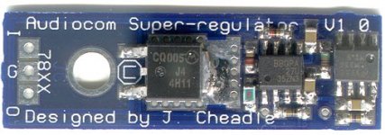
Nice piece of engineering altough the cap at the top isn't soldered!
The pcb has groundplane which is connected to "in".
Fred, Audiocom's regulator is pure Sulzer regulator, LM336 2.5 volts, OPA27 and the opamp is feed from the unstablized side.Fred Dieckmann said:Has anybody asked Walt Jung about using his design (and it sure looks like his design to me) for commercial purposes? A magazine is selling the boards for his regulator with his permission if i am not mistaken.
I know you have the mounting foot print but, do you really think that thing is going to fit in someone equipment as an after market mod? ITS HUGE
You might want to see what the competition is doing..........
Nice piece of engineering altough the cap at the top isn't soldered!
The pcb has groundplane which is connected to "in".
Attachments
What happened to your regulator. Not alive yet? Coming soon... 2003dipchip said:Hi everyone,
I have completed the layout for a 3-terminal Super Audio Regulator. (I Hope!)
The design was very generously given to me by ALW.
from ALW Audio
I modified his design slightly to make it fit into a 3 terminal
78xx and 79xx footprint. (But I still have the original option of
the sense pins, if you hardwire them)
This voltage regulator has a normal linear pre-regulator that could be removed if needed, followed by a Walt Jung super low noise voltage regulator.
Dale (harvardian) and I, are going to try to offer this board (and a negative version) as a kit.
I named it the APOX-JR+ and APOX-JR-
I posted pictures of the layouts, so I would really like some feedback before I finalize the board layouts.
You can see the designhere
Is anyone interested in a board like this?
Thanks,
Craig Beiferman
What happened to your regulator. Not alive yet? Coming soon... 2003
It's hiding....... trying to keep from becoming your (and others) regulator.
I have a design but am thinking of writing an article for one of the audio hobbyist magazine or websites. I don't know if it would be suitable for this forum since it is a shunt regulator and assumes knowledge of the load AC and bias current as well as proper heat sinking.
Maybe a little more useful here would be a modification of the "three terminal IC type" with a power IC and an external voltage reference. I have a device picked out and may have the prototype under test this week or early next week. The adventure with the nose set me back about 6 weeks and home and car repair has pretty well shot most of this week. I sound like Grey..... maybe I will cut him a lot more slack next time the issue of delay due to more pressing commitments to more pressing issues surfaces. Good picture of the Audiocom regulator. I missed it. They have another one that is supposed to be much better.
Re: Re: Who's design
I used one to power an XO. Totally useless, spews out harmonics like a sick man. With a resistive load, all is sweetness.

----------------------------------------------------------------------------------peranders said:
Fred, Audiocom's regulator is pure Sulzer regulator, LM336 2.5 volts, OPA27 and the opamp is feed from the unstablized side.
Nice piece of engineering altough the cap at the top isn't soldered!
The pcb has groundplane which is connected to "in".
I used one to power an XO. Totally useless, spews out harmonics like a sick man. With a resistive load, all is sweetness.
spews out harmonics?
Sounds like instability to me. Does this thing have any Elko (electrolytic) bypass caps on the board. Ones on the main PCB are going to be too far away. Anyone who plans on building a three terminal regulator replacement board had better try stay close to the foot print of a TO220 device. These things seen to be stuck pretty close to their filter caps and even each other. A big PCB (relative to the size of TO220 package is not going to fit in many if not most products. I would go SMT for everything but the elko filter caps. These I would mount on the other side of the board, using radial caps but laying them down flat against the PCB and securing them with a small dab of RTV (Silicone sealer) This circuit could be done if the preregulator circuit is not used, but is still a daunting task for a good layout with a small footprint and component height. Just because the Audiocom is not a good design, I wouldn't rule out a drop in board for TO220 device replacement. It can be done. In absolute seriousness, I think this would be a good project and be extremely useful for updating equipment with tight real estate requirements around the Three terminal regulators. If anyone is interested (yes you too P-A) I will be happy to offer further advice.
Sounds like instability to me. Does this thing have any Elko (electrolytic) bypass caps on the board. Ones on the main PCB are going to be too far away. Anyone who plans on building a three terminal regulator replacement board had better try stay close to the foot print of a TO220 device. These things seen to be stuck pretty close to their filter caps and even each other. A big PCB (relative to the size of TO220 package is not going to fit in many if not most products. I would go SMT for everything but the elko filter caps. These I would mount on the other side of the board, using radial caps but laying them down flat against the PCB and securing them with a small dab of RTV (Silicone sealer) This circuit could be done if the preregulator circuit is not used, but is still a daunting task for a good layout with a small footprint and component height. Just because the Audiocom is not a good design, I wouldn't rule out a drop in board for TO220 device replacement. It can be done. In absolute seriousness, I think this would be a good project and be extremely useful for updating equipment with tight real estate requirements around the Three terminal regulators. If anyone is interested (yes you too P-A) I will be happy to offer further advice.
Boss.... da plane, da plane!
"The pcb has groundplane which is connected to "in" - P-A/
I am pretty certain that is not a groundplane ( its not connected to ground for one thing) The pass transistor is SMT and the surface area of the "plane" is connected to the collector: It is a heat sink using the
PCB "plane" area.
Go read some ap notes for SMT power transistors and this trick is explained in more detail. The Zetex website has some good info on this I believe, since I saw some stuff on this in one of their data books. Maybe it doesn't get warm enough in Sweden to worry about this, but it sure does in Texas!
Later,
Tatoo
Fred, the IN-pin is connected to the backside (plane) which is connected to the collector which is connected through 15 vias. The power plane has only one trace. It's the power to the reference from the real output. Otherwise it's a whole power plane which, Fred I know, serves as a heatsink. Fred, I won't have to read books for seeing this.... I'm using my eyes only, because I'm holding the regultor in my hand.
About decoupling caps: How many do you see? Correct not too much. It's the one which unsoldered at the picture. The GND trace is a thin (15 mil!) trace along the sides of the pcb.
I can imagine that this regulator is not very well suited for difficult loads.
About decoupling caps: How many do you see? Correct not too much. It's the one which unsoldered at the picture. The GND trace is a thin (15 mil!) trace along the sides of the pcb.
I can imagine that this regulator is not very well suited for difficult loads.
Re: What happened to your regulator. Not alive yet? Coming soon... 2003
He, he, you are joking again but why don't you do something. It might be interesting.Fred Dieckmann said:I have a design but am thinking of writing an article for one of the audio hobbyist magazine or websites. I don't know if it would be suitable for this forum since it is a shunt regulator and assumes knowledge of the load AC and bias current as well as proper heat sinking.
Re: Re: supply
Hi Elso,
Saying you tried it doesn't say anything really. What was the result, did you compare the two methods, how did you decide that one was to be preferred over the other??
Jan Didden
Elso Kwak said:
But you are wrong, Jan (and Lars too). Just tried it!
Hi Elso,
Saying you tried it doesn't say anything really. What was the result, did you compare the two methods, how did you decide that one was to be preferred over the other??
Jan Didden
Re: Re: Re: supply
I have no comment, deleted my post.

Jan,janneman said:
Hi Elso,
Saying you tried it doesn't say anything really. What was the result, did you compare the two methods, how did you decide that one was to be preferred over the other??
Jan Didden
I have no comment, deleted my post.
- Status
- This old topic is closed. If you want to reopen this topic, contact a moderator using the "Report Post" button.
- Home
- Design & Build
- Parts
- 3 terminal Jung Super Regulator Kit