Hi Traderbam,
Your suggestion is as good as any really. I sometimes try to think of this as a DC problem, putting in high values (say 1 ohm) for wiring to see what really happens.
Separate wires to the star would need careful routing so as not to pick up any stray fields.
As you say even the star itself is problematic, you can never get to a single point. Must come pretty close though.
I keep going back to all those articles of D Selfs, can he have got it so wrong ? or is it me and my understanding thats flawed.
At one point I even made a "model" of two OpAmps (5534 with a bit of drive capability) on two PCB's with 47 ohm resistors in all ground connections to try and come up with a layout that did not interact. There are so many pitfalls along the way. As you say each and every bit of print and wire has significant resistance.
Attachments

Mooly said:. . . I tried everything I could think of on Dougs amp. . . .
So did I. Did you try grounding the speaker onto the potentiometer and also incorporate Dr. Cherry's tapping point? You get. . . Audio Ramjet! LOL!
The speaker - is getting into the amplifier + input via both potentiometer and input load resistor. For reference, there's a DC block cap in-between those two loads.
Its a dynamics boost for sure. There's larger differences between playback volume for different tracks. As if chest-thumping bass from a teacup size 16w amp wasn't enough clue that there was a pretty big difference.
This just got fun. THANKS GUYS!!!
So, it seems that if there's no way to keep the AC coming off the speaker - from getting into the amplifiers - input. . . then throw some down the + input as well. Is that what I did?
AndrewT said:
But I cannot recall anyone suggesting where best to tap off
both the upper leg of the NFB and the lower leg of the NFB.
Hi,
As far as I'm concerned D.Self covers both the "correct" output point
and the correct earthing arrangements for the inputs and feedback.
That is the inputs and feeback network are on a seperate
earth return to the earth return of the amplifiers load.
Consequently the feedback encompasses the load return.
") /sreten.
/sreten.Hi Sreton,
I have the greatest respect for Dougs articles over the years -- they really should be required reading whether or not you ultimately agree with some of his conclusions.
It's this "two amps" together bit that I have a problem understanding.
What you say makes sense, but is this what I have drawn ?
What am I not seeing here.
This is Dougs approved layout and grounding scheme.
Getting just one amp in isolation to perform impeccably is easy. Its when the two are coupled together the fun starts. The PCB's are approved by Doug and have the input ground and speaker ground as I have drawn them.
This is something I want to understand
Regards Karl
Hi,
Your diagram is the wrong way to do it according to D.Self AIUI.
The earth reference point for the inputs and feedback should
be entirely seperate back to the star point and the star point
arranged for minimal interaction between any currents.
/sreten.
edit : I have not analysed published PCB layouts
Your diagram is the wrong way to do it according to D.Self AIUI.
The earth reference point for the inputs and feedback should
be entirely seperate back to the star point and the star point
arranged for minimal interaction between any currents.
/sreten.edit : I have not analysed published PCB layouts
Mooly said:Eva, Wavebourne, AndrewT, Daniel and all,
What's your take on this ?
This follows D Selfs work on his blameless amps and is the arrangement Doug recommends. Each amp is discrete, the grounding line on the PCB follows that in my drawing. The speaker ground is as shown on the PCB.
What I can't grasp is this. In isolation ( as a Mono amp )each amp is perfect.
What happens when the the two input grounds connect together at the source.
If the top amp is supplying say 5 amps positive into the load then the ground lead to the star will have a volt drop along it with reference to the star. No problem in itself. The lower amp will be at a different ground potential to the upper, so what happens when those input grounds connect. To me an unwanted volt drop is now developed along the ground track of both amps.
Hope you can follow that. This is something that really bugs me, I can't grasp this.
To me the speaker return should not be on the PCB for a stereo pair on a single PSU.
Help
My take on this is, D. Self should think a bit more to understand, is he designing a stereo amp, or 2 separate mono amps?
Sometimes people read popular technical literature like they read Bible...
--10 commandments?! Why so many?
-- Don't argue, Moses!
--Hmmm... Is it the 11'th Commandment?!
Mooly said:. . . What am I not seeing here. . .
Opinion:
That was supposed to have been monoblocs / dual mono.
I think that he liked the sound of the design and didn't change it for the stereo amp. Its quite possible that the original design was a single monobloc.
You can tell if this was accident, because the wiring as pictured will inspire some additional DC offset--perhaps too much. Is he using a DC servo? EDIT: Or is there large capacitance at the amplifier boards?
sreten said:Hi,
Your diagram is the wrong way to do it according to D.Self AIUI.
The earth reference point for the inputs and feedback should
be entirely seperate back to the star point and the star point
arranged for minimal interaction between any currents.
edit : I have not analysed published PCB layouts
Hi Sreton,
I have in front of me the approved wiring scheme by D Self. I built the amp on the PCB's supplied by "The Signal Transfer Company" which were fully approved by Doug. The PCB grounds are as my drawing in post #14. The ground track on each PCB is essentially just a run of print from end to end. Input ground at one end, speaker return at the other together with the ground connection to go to the star earth.
Doug then shows the two input grounds wired together ( which I have not shown ), but these do not connect back to the star point.
This is what I do not understand. To me the input ground and NFB return should be referenced back to the star, and not form part of a loop-- as you suggest.
If you email me I can send you a copy of the layout.
Maybe there is something so obvious here I just can't see it
Hi Daniel,
No servo -- The DC offset is determind by the circuit topology and matching of the input devices. It's very good in that regard, I got mine down to around 5 mv I think through careful matching.
There are no large capacitances on the PCB, 220 mfd from memory, but even this must couple rail disturbance into the common ground.
In many ways the more ideal solution is to have left and right amps on a common PCB.
Take a look at Syn08's grounding scheme on the PGA website.
Since THD and noise on this design is <1ppm, you can be assured he got it right.
From my side, in my earlier days, I had a lot of fun trying to get rid of EL's in amplifiers. One of my earliest efforts was the 'Equa' amp published in Elektor in the mid to late 1970's. That thing buzzed and hummed - but it was my wiring that caused it. A few years later I ended up designing low noise linear circuitry for instrumentation, A-D's and some SMPS. Henry Ott's book and some guidance from more experienced engineers help me turn Ott's EMI theory and my college theory into practice. I ended up a year ot two later with a thermocouple amplifier feeding a 16 bit A-D converter via an amplifer sitting right next to a 10W SMPS running at 100kHz. No noise problems and it was all down to layout. No screening either.
In my amp now, I take the speaker gound returns back to star ground. The filter capacitor returns also connect at the star ground - so you have two loops - the PSU loop and the amp/speaker loop that connect at one point only and that is the star ground. This keeps the cap charging currents completely separated from the amplifer/spkr signal loop. The VAS and drive r stage grounds (coupling caps, VAS load resistor which I use in my design etc) connect together on the PCB and then via a dedicated line to the star ground. The input signal ground, and feedback network ground point are separated from the amplifer ground mentioned above by a 22 ohm resistor. I tried 10 Ohms -also works well with no change in performance. I have not tried removing this resistor altogether - but I dont expect any real problems.
The amp is completly silent with respect to buzz/hum etc - you can stick your ear against any one of the drivers and its quiet (and yes, it is ON)
One other point - keep all current loops small (i.e. compact) as possible - so return traces must be right next to supply traces on your pcb. Keep the + and - supply lines to the amp apart (to avoid amplifer guru's 'spray harmonics' and induction into the other supply line and small signal stages.
Good luck with your project.
Mooly said:
Maybe there is something so obvious here I just can't see it
Hi,
Maybe I cannot either
. Thinking about it I'm disagreeing with myself ... /sreten.Hello Bonsai,
What you describe sounds to me to be the correct way. The speaker currents have to be kept separate. So too, the rail decoupling. In fact anything that can cause a volt drop "across" the input ground and feedback connections. You have to treat each conductor as a potential source of trouble. You have to keep going back to first principles to see what the amplifier output is trying to do in relation to the input signal and feedback signal and whether those very signals are being altered by unwanted currents.
When I look back on my first amps, hum/noise were always the big problem. When I made my latest Mosfet amp, I actually built as I mentioned earlier two small "models" to investigate this.
The layout I came up with is so at variance to D Selfs layout etc that I started to question whether I was "missing the point" somewhere.
You have to trust your instincts I guess
Mooly said:Hi sreten,
Email me, I have the page next to me with the layout -- see what you think. Am I overlooking something ?
Hi,
Why I'm dissagreeing with myself is what should the feedback be
referenced to ? the star point or the earth speaker terminal ?
I think it is the speaker terminal ......
I'll have a look again at D.Self books this weekend.
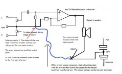
/sreten.I can't figure this out either. But, if you throw the noise from the speaker return (load ground) down both the + and - inputs on the amplifier like this http://www.diyaudio.com/forums/showthread.php?postid=1623002#post1623002 then is it a cancellation or is it amplified?
That sketch isn't a recommend. It is a question.
EDIT: Not shown is the potentiometer at the "X" terminals.
And, if that's done in stereo layout, does it matter how much the "other" channel lifts the voltage up and down--because that may only slightly raise or lower the gain (stereo expansion)? Well, I don't know. So that's why they're questions.
OK so far...Bonsai said:...
One other point - keep all current loops small (i.e. compact) as possible - so return traces must be right next to supply traces on your pcb...
but I believe this last part is wrongKeep the + and - supply lines to the amp apart (to avoid amplifer guru's 'spray harmonics' and induction into the other supply line and small signal stages.
Class B ps currents are individualy very nonlinear but when routed (twist or star quad) close together the far field from the sum of the +/- ps currents should be as linear as your load impedance
spacing +/- supply traces apart maximizes the nonlinear field coupling area
as per the 1st statement it also helps to have the ps gnd return near the closely coupled combined ps leads
and of course bridge drive doesn't have significant return current in "gnd" so close coupling the ps leads is the only way to go
Remember this is for running TWO amps off a common PSU.
This is how I see it. We have to have a single point of reference for both channels. In a way this is a star in its own right. Nothing else should connect here.
Whatever output current the amp sources or sinks this can in no way alter the input reference point ( for practical purposes, as even the small current in the feedback return does flow down the blue connection to the star earth).
When all this is drawn out it all looks very straightfoward but as I keep banging on, to me this is so at odds with DSelfs layout.
Attachments
The Blue signal ground is connected to a very low impedance.
Does this make it less susceptible to either form of magnetic/electric interference?
referring back to post 39.
The two input RCAs have to be commoned at the terminal panel to allow a single Signal Ground connection back to the two channel Audio Ground.
Does this make it less susceptible to either form of magnetic/electric interference?
referring back to post 39.
The two input RCAs have to be commoned at the terminal panel to allow a single Signal Ground connection back to the two channel Audio Ground.
- Status
- This old topic is closed. If you want to reopen this topic, contact a moderator using the "Report Post" button.
- Home
- Amplifiers
- Solid State
- 3 stage LIN topology - NFB tappings?