It's not new tech and back in the 70s and 80s there were some very advanced drive setups from Japan for the big DD turntables. But for belt drives cheapy AC motors were, well cheaper so some of this was forgotten.
Nowdays there are solutions galore out there, but a lot of TT manufacturers, having spread FUD over DD in its heyday (Linn I am thinking of you here) don't want to admit that there is better.
We have much better (may be 10 times) more advanced in the DD motors tech and bearing tech. I think we should be able to produce the best DD motors today. But the demand is low so the cost per motor would be high to attract the motor manufacturers to revise / design and implement the DD motors line again.
The BLY172S24V2000 is a 40W motor; what are you hoping to drive with it?
The SG4 could be used to drive an amp for this motor, but you need to send a chip back to me for reprogramming (right now, it just goes down to 40Hz, but not below).
The winding resistance is 1.6 Ohms, so it may be challenging to drive it.
The SG4 could be used to drive an amp for this motor, but you need to send a chip back to me for reprogramming (right now, it just goes down to 40Hz, but not below).
The winding resistance is 1.6 Ohms, so it may be challenging to drive it.
Hi Bill
I am using AC motors now and have a minimum amount of knowledge about them. This 3 phase running Bldc motors I know nothing about. You seemed to like them so I thought it would be great to try. The motors you used looked to be 6 ohm resistance vs the 1.6 on the one I was looking at. Is that the load the amps see. AC is a whole other ball game. The one amp section I am using has 3 150 watt into 4 ohms and If I remember stable to 2 ohms. This runs the 50 watt papst synchronous motor fine.
The 32 and 38 pound platters seem to like the extra HP. If you ran the motors at 700 to 800 rpm would that give the sg4 the down adjustment to 40 Hz that you might need for pulley diameter/platter diameter etc?
Thanks for help
Tom
1.6 Ohms is what each amp will see at start up and at low speeds. As the speed increases, so does the impedance and you need to increase the voltage to maintain rated torque, so the impedance should remain fairly constant through-out.
A heavy platter only requires a lot of torque at start up; running torque needed is greatly reduced. On the BLDC controller, I start the platter at ~5 RPM so the torque requirement is also greatly reduced.
If you run the motor at 800 RPM (and machine a pulley to reduce that to 33.33 RPM) that would put the SG4 output at 53.33 Hz which should give you plenty of adjustment range.
Hi Bill
Going to order a bldc motor today. Been researching loads on amps, motor loads, etc but you are the go to guy on this 3 phase bldc motor stuff. Nobody else I could fine has done this or knows any of the in or outs. The Audio community is luckily having someone like you pushing the edge.
So if the class d amp is OK with a 2 ohm speaker load (which can be all over the place); will it be OK with the 1.6 line resistance of the one motor or there was another bigger motor with 2.1 line resistance? I am willing to experiment to see if the bigger motors will work well in this environment.
Thanks Tom
Hi Bill
Got around to building a new controller for a brushless DC motor. I thought
I would go with the 41 watt larger one. I also went with a 40 to 115 step up trans to let the amps see a 4-5 ohm load.
Everything is running smoothly but I can not get a correct reading on voltage on the motor side. With 8 to 9 volts out of the amp I should be getting around 24 at the motor. Instead I am showing 5 to 6 depending if I use delta or wye feeding it. The motor starts right up and runs smooth and quiet. The amps are running cool.
Was talking to a buddy and he thought maybe back emf from the motor is causing the fluke 87 to give bogus readings at the motor. The reading on the 3 phase papst motors check out. Is there something about the bldc motor that is fooling the meter. It seems like everything is alright but would like to know what voltage the motor is actually seeing.
Very nice powerful motor is a small package. Now I just need to figure out how to measure the voltage the motor is seeing.
Thanks Tom
If you are running a 24V BLDC motor, you most likely don't need a step up xfmr between the amps and motor. If you are using the xfmr to step up the voltages, it will reduce the impedance seen by the amps. If you are using it as a step down, it will increase the impedance but lower the voltage. You will not need 24VAC to run the motor. At full speed you will need ~24VPP or 8.5VRMS on each winding.
Which amps are you using? Are they single ended or BTL?
Do you have a wiring diagram showing SG4, amps, xfmr and motor?
Which amps are you using? Are they single ended or BTL?
Do you have a wiring diagram showing SG4, amps, xfmr and motor?
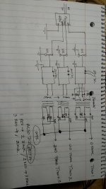
Hi Bill
Do not have schematic software so a did a quick drawing. The frequency gen was the Chinese one I was using on the test bench. The sg4's are in my playing system.
These are the parts. Anaheim automation bly172s-24-2000. Sure aa-ab31282 btl 200 watt 15-36 DC input stable to 2 ohms. Antek as-0540 /40 to 115v in step up.
I do have 5 ohm thermistors and by pass relays in circuit. I already had them so I thru them in. Not shown on schematic. The reason I used a 2.875 step up transformer was to get the load of the motor to the 4-8 ohm mark so the amps would be happy. So if I did this correctly. 24 volts squared 576. 41 watts ÷ 3=13.66. 576÷13.66= 42.17. Step up 2.875 squared = 8.27.
So 42.17÷8.27=5.10 ohms the amps sees. If you see a problem with the numbers and conclusion please let me know.
The numbers , when I checked the voltages all seemed OK until I got to the output side of the transformer feeding one phase of the motor. With .280 RMS feeding the amps the output was 8.77 rms. With 8.77 rms feeding the 2.875 step up transformer the meter was only getting 5.9.rms .
I am feeding the green/blue wires in parallel and taking the output from the red/black wires in parallel. So green to positive and blue to negative of amp. Red output to phase wire of motor and black either connected together or delta where red of one to black two etc.
The motor has its black wire to red output of trans 1. Red motor wire to red trans 2 and yellow motor wire to red trans 3. Seems to be running fine in the right direction. So I am confused why I can not get a correct voltage reading at the motor.
If I ran the motor with out the step up transformer would the amps see a 42 ohm load. I am getting 31 step up on the amps running 24 v DC input. I can get 24 rms to the motors no problem but I was concerned about the 42 ohm motor load on the amps.
Bill I am all ears. You maybe the only guy on the planet who has gone down this Bldc run on 3 phase AC path. The only things I can come up with is back emf or transformer saturation for this motor voltage reading.
As always thanks for all the help.
Tom
Attachments
You are making it much more difficult than it needs to be. For one thing, you are crossing back and forth between DC commutation methods and sinewave drive.
You cannot compute the power the way you did by simple math. If driven by commutating DC, one coil will be driven positive, one will be driven negative and one will be off. They will all be out of phase with each other and constantly changing as the hall sensors inform the controller when to switch. If you drive the windings to 24VDC level, the motor will be at spinning at rated speed (2000 RPM or most likely, higher) and there is a lot of really complex math going on.
The data sheet tells you what the DC winding resistance is: 1.6 Ohms. This is what each amp (or xfmr primary) will see at zero (or very slow) speeds. You could try to compute the voltage needed for each winding (at very low speed) to produce 40W, but there are lots of variables and the math is not trivial. To further complicate matters, the impedance changes as the motor increases in speed. A much simpler way is to measure the power consumption and adjust the drive level until you have 40W at the desired speed. You can measure this at the power supply output and factor in the amp efficiency and transformer losses. At 800 RPM (IIRC to get 33 RPM platter), I would guess you would see 10-12VPP or 3.5-4.25VRMS. If you run the motor at 40W all the time, I would think it would get quite hot, the case temp topping out at 150°F or higher. You certainly will not need that much power once the platter is turning and I would suggest dropping the drive level down until power consumption drops by 25-33%.
You can (and should) get rid of the transformers, they are making everything more difficult. FYI, the turns ratio is probably closer to 2.3:1. Disconnect a xfmr from your circuit and measure the primary side input voltage (120VRMS) divided by the secondary output voltage with no load; this will be much closer to your turns ratio.
If you don't use xfmrs, you will not be able to use BTL amps to drive this. You can still use class D, but they should be single ended outputs. TI make some of these chips and there should be ready made amps available on e-Bay. I think the TPA-3123 is 50W/channel, runs from 24VDC and is SE output. If you can't get SE output amps, then use isolation transformers with a 1:1 turns ratio. I have no experience with delta configured outputs. I would wire the xfmr outputs as wye configuration; if nothing else, it eliminates any currents that can circulate within the delta loop.
If you use the SG4 to drive this, you should not need the thermistors as the voltage ramps up from zero to max, and you can program a reduced voltage after the platter is up to speed (5 secs).
Last edited:
Hi Bill
Thanks for all the information. Seeing I have the parts already would like to try to use them. If I do the testing and adjustments to get the motor to 25 to 33% of wattage and set the hz to get 800 rpm, what do think the load would be to amps without transformers. I can do the math on the step ups. The measurement on the transformers out of the circuit is with no load 121 in 43 out so 2.81.
The interesting thing is with 8.77 RMS out of amps to the transformers, the motor seem to run great, could not stop it with my fingers, ran it for maybe 5-10 minutes and with room temp at 80 the case was 95 degrees and heat sinks on amps where at 100.
So if the 2.81 step up transformers bring the impedance down below 2ohms and I keep the amps and go to a 1 to 1 transformer would you go 25 va or 50. With all this crazy math I am at a loss. I guess if you can give me a ballpark of what you think the impedance will be with above numbers I can test and measure the other information that you gave me.
Thanks Tom
If the amps are running hotter than the load, that's a pretty good indication that there's a mismatch. Even at class AB (50% eff), they should be pretty close to the same temp (assuming proper loading). Your amps are 90-95% efficient. On my BLDC set up, the motor will hit 140°F at 12-15W, but the amps never get above 100°F. My guess is your motor is loading down the primary outputs of the xfmrs, which is why the voltage is so much lower than expected.
Using 1:1 xfmrs, you might want to go with the larger version. 25VA would give you slightly less than 3dB of headroom. I think the load will be OK with the amps you have. The impedance will not drop below 1.6 Ohms and will always be higher as the speed increases. That is why the drive voltage must increase as the motor speed increases.
IIRC, these motors are around 35-45% efficient. If they consume 40W, then 22-26W will be lost as heat. I would expect case temps higher than 95°F.
Hey Bill
Looking at 50 va transformers 115 to 115 v. They spec them at 50 and 60 hz. Might go in the 40's to get the rpm I want, any issues there? Also antek 115 to 115 has couple of 6v outputs so the price jumps up a lot. Found some triad n68x 50 va c core normal wind for half the price. Any pro or con's with this vs toroidal in this application?
Thanks Tom
I thought you were going to machine a pulley so the motor would run ~800 RPM with a frequency of ~53Hz?
The xfmrs aren't going to like 40Hz and there may be stability problems with the amps and the xfmrs at that low of frequency. I would expect losses and distortion to go up.
Laminated xfmrs can buzz sometimes, depending on the quality (just ask VPI ), but they don't have core memory like toroids, the latter not being a problem if you ramp the voltage at start up.
The xfmrs aren't going to like 40Hz and there may be stability problems with the amps and the xfmrs at that low of frequency. I would expect losses and distortion to go up.
Laminated xfmrs can buzz sometimes, depending on the quality (just ask VPI
), but they don't have core memory like toroids, the latter not being a problem if you ramp the voltage at start up.
Last edited:
Hi Bill
Thought I would play around , while the new transformers are in transit, to see if lower input to transformers would stabilize things. I also thought throw the ac current clamp meter on.
This is the outcome. Out of amps 4.89 rms volts showing 1.12 amps on clamp meter.
Out of transformers 4.63 rms volts and .63 amps. The switching power supply showed 122 volts at .42 amps ac. The motor needed to be helped to start and could stall it easily with your fingers, at these voltages.
So as the power out of the amps is reduced the reading out the amps is getting closer to transformer out. But instead of equal it should be 2.8 times higher. Could it be that if the step up transformers are dropping the impedance to under 1 ohm to the amps, that the transformers are consuming all this power?
Thanks Tom
The xfmrs shouldn't consume any more power than the IxR losses in the windings and core losses between the windings. What your readings indicate to me, is the amps are working real hard and not delivering much power to the loads, they will consume the excess. Which is probably why they are getting hotter than the motor. This should never happen if the amps are 90% efficient and the motor is 35% efficient.
I'd be careful about reading too much into the numbers you are reading. If you don't know what the power factor is, they start becoming confusing if not meaningless.
I don't mind answering questions where I can, but I feel like you want me to design a controller built to your specs, even though I would never design what you are asking for. I can't make a silk purse out of a sow's ear. I already told you how I would design a 40W controller, but it is only a starting point. Even if I were to design one, I would most likely encounter some of the difficulties you are seeing and have to adapt accordingly. This is difficult enough to do when I'm working hands-on, it's nearly impossible to do through the web.
I'm not trying to discourage you and I don't mind troubleshooting something I designed, but I have limited resources to clean up someone else's design.
Not trying to derail the thread or anything, just saw this video and thought I would share it for those who have not seen it.
https://www.youtube.com/watch?v=EjrEnxXnTk0
https://www.youtube.com/watch?v=EjrEnxXnTk0
- Home
- Source & Line
- Analogue Source
- 3 Phase BLDC motor for turntable use?