Member
Joined 2009
Paid Member
my guess (haven't tried it) - Whilst most of the filament hum is also at the same frequency as the B+ ripple I would doubt very much that they are aligned in their phase. This means the simple L-W approach would not be able to null out the filament hum, although it may be able to reduce it.
I don't think L-W can null out all the B+ noise either, perhaps 20dB to 30dB is realistic ? - and this can be achieved with RC or LC in the B+ line too. Maybe somebody who's built the L-W can comment on its effectiveness - has Sheldon made measurements ?
I don't think L-W can null out all the B+ noise either, perhaps 20dB to 30dB is realistic ? - and this can be achieved with RC or LC in the B+ line too. Maybe somebody who's built the L-W can comment on its effectiveness - has Sheldon made measurements ?
Last edited:
Does the Loftin and White circuit compensate for filament hum or are you implementing DC heating? On Correlation Between Residual DHT Filament Hum and AC Frequency. Distortion-induced hum in directly-heated triodes.
Hello,
No, LW compensates only for power supply ripple.
We specifically select tubes like Type 45 or a 2A3, so we can use AC heating, which is superior sounding to DC heating, and desirable to employ. We can "live" with a little bit of filament hum, in exchange for the better sonics obtained with AC heating of 2.5 VAC filaments.
Jeff Medwin
B+ hum for the typical full wave rectifiers of the day is at double the mains frequency. So L-W can't compensate for heater hum. Phase and waveform / shape are further issues.
To compensate for heater hum, you need to pick up the heater ac directly from the heater winding and inject it, L-W style. Look at Darius' blog for a way to do that.
That being said, I'm not totally convinced by that, and DC heaters are probably the more legit approach.
To compensate for heater hum, you need to pick up the heater ac directly from the heater winding and inject it, L-W style. Look at Darius' blog for a way to do that.
That being said, I'm not totally convinced by that, and DC heaters are probably the more legit approach.
Last edited:
B+ hum for the typical full wave rectifiers of the day is at double the mains frequency. So L-W can't compensate for heater hum. Phase and waveform / shape are further issues.
To compensate for heater hum, you need to pick up the heater ac directly from the heater winding and inject it, L-W style. Look at Darius' blog for a way to do that.
That being said, I'm not totally convinced by that, and DC heaters are probably the more legit approach.
Indeed that thought crossed my mind; I must study Darius's blog.
Further reading: Effects of AC Heating Power Applied to Directly Heated Triodes
I don't think L-W can null out all the B+ noise either, perhaps 20dB to 30dB is realistic ? - and this can be achieved with RC or LC in the B+ line too. Maybe somebody who's built the L-W can comment on its effectiveness - has Sheldon made measurements ?
If everything is perfectly aligned you could probably sim perfect cancellation. But in real life there will be small phase shifts (e.g., the cap in the cancellation string). I didn't do any careful measurements, just looked at the scope and dialed in the cancellation.
Sheldon
my guess (haven't tried it) - Whilst most of the filament hum is also at the same frequency as the B+ ripple I would doubt very much that they are aligned in their phase. This means the simple L-W approach would not be able to null out the filament hum, although it may be able to reduce it.
I don't think L-W can null out all the B+ noise either, perhaps 20dB to 30dB is realistic ? - and this can be achieved with RC or LC in the B+ line too. Maybe somebody who's built the L-W can comment on its effectiveness - has Sheldon made measurements ?
I've been running a supply that has a solid 3 VAC of ripple and it has no hum (simmed and measured). No, I can't hear any hum... I'm running 2a3's on AC filaments too but no hum. Very close to the speaker it did have a very faint buzz when I used cheap commercial tranformers (tomiko, 6 Watt things).
With the superb quality J&K OPT's I now have hooked up it is darned near silent with my head right beside the speaker. I have the 2a3's biased to draw 50mA. Using the 6SL7 in the bootstrapped follower topology so I am really getting close to full power out of these cheap terrible chinese 2a3's. The sound is Extremely GOOD! Far more power than I need for my 94db speakers too.
My Lundahl choke has two windings, so I initially split the windings - one for each channel. But just to see how far I could push it, I put the windings in parallel. This resulted in about 6 VAC of ripple....
 That proved too much though - I couldn't quite cancel out 6 VAC using the Loftin-White Topology. Still sounded fantastic, but there was a tiny hum.
But hey... 3 VAC in the B+ and no hum? Good luck beating that.
I'm working up a better, faster power supply with far less ripple just because it makes sense. Hope that answers your question!
Ian
Last edited:
Member
Joined 2009
Paid Member
Hey that's good information! - so we want to see 3Vac or less on the B+ in the finished article for 94dB speakers. I assume more sensitive speakers means setting a lower target.
I also have 98 dB speakers in my office... full range.. no hum with them either! I don't think it really has much to do with speaker sensitivity...
Member
Joined 2009
Paid Member
The question remains - is the L-W topology better ? Given that we have access to very good quality passive components that L & W did not, we can build a power supply with sufficiently low ripple. Neither are we subject to commercial constraints and we can choose to spend freely on our projects. If our goal is the best sound then the jury is still out as to which approach is preferred.
Why would we not choose the L-W topology ?
a) raises the output impedance of the first stage (reduces tube choice for good h.f. response)
b) it 'recycles' the B+ noise through the input tube with its associated non-linearity
Why would we choose the L-W topology ?
a) it allows for a lower cost power supply
b) eliminates the cathode bypass capacitor on the first stage
c) It burns significantly more power in cathode resistor than the usual auto bias power stage.Why would we not choose the L-W topology ?
a) raises the output impedance of the first stage (reduces tube choice for good h.f. response)
b) it 'recycles' the B+ noise through the input tube with its associated non-linearity
c) actually, it kind of eliminates the cathode bypass cap from the power stage as well. Or the psu final cap from the audio path. Depends how you want to look at it.Why would we choose the L-W topology ?
a) it allows for a lower cost power supply
b) eliminates the cathode bypass capacitor on the first stage
Member
Joined 2009
Paid Member
c) It burns significantly more power in cathode resistor than the usual auto bias power stage.
A good point, it's a quite a bit of heat although I've seen Russian designs that use stacked power supplies to avoid it.
However, I am still thinking of a dc-coupled design, just considering the pro's and con's of doing dc-coupling with / without the L-W noise cancelling items ?
If you stack psu's, you need to regulate the ripple on the input stage to zero. You cannot cancel different ripple from two different psu's between stages.A good point, it's a quite a bit of heat although I've seen Russian designs that use stacked power supplies to avoid it.
The big pro of L-W is the low overall parts count and reduction of parts in the audio path, and the modest demands for the size of components and the PSU.However, I am still thinking of a dc-coupled design, just considering the pro's and con's of doing dc-coupling with / without the L-W noise cancelling items ?
Thanks and a Loftin White question .......
Hello All,
In this thread’s post 202, Sheldon writes “TAC” ( triode amplifier characteristic ) is essentially Ra divided by Rp of input tube . The Darius formulas, defining TAC, however, appear to be somewhat different, more complex, than Sheldon’s method, after an initial cursory look.
Are you feeling “correct”, Sheldon, with what you wrote ?
If so, the high mu 6GK5 triode suggested by mach1 seems like a reasonable input tube candidate, usable with a variety of finals, 6AH4GT, 2A3 etc. , ( especially IF one seeks to avoid a bootstrap / cathode follower middle stage, …..which I do.) Thanks again mach1.
From the 6GK5 characteristic charts, ( at 4.5 mA ) I eyeball a mu of 67 and a Rp of about 11,400 Ohms. With the 52,767 Ohm computed plate resistor, Sheldon’s method of dividing the Ra by the Rp of 11,400 Ohms gives a “TAC” of about 4.63, exceeding Darius’ 4.00 minimum .
Kudos. This particular DIY thread, over the last few weeks was great stuff - educational to me, and others. The question is, in this proposed and attached schematic ( below) , am I doing L-W right ?? Its almost time to “pull the trigger” and buy the parts. If anyone sees ANY errors in this, please let me know !!
I am satisfied with the raw B+ supply design with (1) just 24 Ohms of series resistances from three chokes in the B+ filter, (2) under 0.8 VAC of ripple, and (3) 200 milliseconds - for a very smooth full-settle after a 15% current step. That is fine…..
What about the audio circuit ? Particularly the L-W part ?? What do you L-W experienced people think ?? Thanks.
Jeff Medwin
Attachments
Member
Joined 2009
Paid Member
Member
Joined 2009
Paid Member
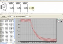
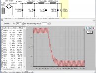
I am satisfied with the raw B+ supply design with (1) just 24 Ohms of series resistances from three chokes in the B+ filter, (2) under 0.8 VAC of ripple, and (3) 200 milliseconds - for a very smooth full-settle after a 15% current step.
And here's an even faster settling time
Attachments
Hi Jeff,What about the audio circuit ? Particularly the L-W part ?? What do you L-W experienced people think ?? Thanks.
Your circuit looks good. Some notes
- B+ must come up slowly, otherwise you will see hot voltages on cold tubes.. In particular, the 6GK5 should come up faster than the 5V3 rectifier.
- Increase your ultrapath cap C4 to 47µF. Otherwise you will see high Zout / low damping factor -> muddy or boomy bass.
- The hum bucking cap C5 can be made smaller, 1µF or 2.2µF would work well.
- Some resistor values are pretty odd.
Full power output will be about 1.2W @ ~6% THD (mostly H2).
Rgds,
GB
In this thread’s post 202, Sheldon writes “TAC” ( triode amplifier characteristic ) is essentially Ra divided by Rp of input tube . The Darius formulas, defining TAC, however, appear to be somewhat different, more complex, than Sheldon’s method, after an initial cursory look.
u of 67 and a Rp of about 11,400 Ohms. With the 52,767 Ohm
I may have over simplified Ra. It's the impedance of the tube with an unbiased cathode resistor (because you get degeneration at the cathode). Darius's formula expresses this. For it to be accurate, you must use the Ra calculated for your operating conditions, which you can get from "average characteristics" on a data sheet. Or by drawing a tangent to the quiescent point of the plate curves, and calculating from that.
Sheldon
- Status
- This old topic is closed. If you want to reopen this topic, contact a moderator using the "Report Post" button.
- Home
- Amplifiers
- Tubes / Valves
- 3 direct coupled 2A3 amps