Whoop - pay day has arrived and I've found a great little place to help finalise the design, do a CAD drawing and the cut/rout all the panels: Fab Lab Ellesmere Port- a digital fabrication laboratory giving businesses, entrepreneurs, schools and communities the tools to turn their ideas and concepts into reality. - Fab Lab Ellesmere Port - Welcome to the Fab Lab Ellesmere Port website. they have branches across the UK and the world so worth a look if you're CAD and equipment challenged like me!
I'm popping down in a couple of hours to re-draw the enclosure and will re-model it to check all will work and then head down next week to do the cutting - the router is booked out all of today for someone who is making themselves a Les Paul guitar.
WRT to bracing I'm planning on increasing the internal width to 518mm to allow for an entire line length section of bracing - this then will be cut to make pieces to disperse throughout the line to strengthen the enclosure. Do you think this would be better, strength/sound wise, than just splitting the enclosure in half between the two drivers creating two separate enclosures mounted on top of each other?
Then I just need to find a final finish acceptable for SWMBO - I have paint facilities available at work so was planning on a high build primer followed by a gloss paint over the top - over an MDF base, I have thought about PLY but worry about voids and availability/cost/finish attainable on it - any suggestions appreciated!
Look forward to giving you all something to look at in the next couple of weeks and something I can listen to shortly")
Thank you for all your help.
I'm popping down in a couple of hours to re-draw the enclosure and will re-model it to check all will work and then head down next week to do the cutting - the router is booked out all of today for someone who is making themselves a Les Paul guitar.
WRT to bracing I'm planning on increasing the internal width to 518mm to allow for an entire line length section of bracing - this then will be cut to make pieces to disperse throughout the line to strengthen the enclosure. Do you think this would be better, strength/sound wise, than just splitting the enclosure in half between the two drivers creating two separate enclosures mounted on top of each other?
Then I just need to find a final finish acceptable for SWMBO - I have paint facilities available at work so was planning on a high build primer followed by a gloss paint over the top - over an MDF base, I have thought about PLY but worry about voids and availability/cost/finish attainable on it - any suggestions appreciated!
Look forward to giving you all something to look at in the next couple of weeks and something I can listen to shortly
Thank you for all your help.
Sorry for the delay in posting, it's been kids party season and all my Saturdays have been taken up with Frozen parties plus the only guy at FabLab who can help me has been off on paternity leave! My birthday this weekend so nothing happening until next...
Update:
Have "finalised" Sketch up drawings, along with cut sheets - would load but can't - says invalid files? Any idea how to load them or link to them?
I'm making an 18mm MDF enclosure and then facing it with 12mm top grade birch ply on 4 sides. The 4 forward faces will be given 45deg angles so the layers of the ply can be seen - final wax/lacquer to be chosen.
I've also included the designs for the Focal Utopia 6W2 TQWT and a side unit to house amplifier and av equipment with storage for my daughter's stuff to the side, again made from 18mm MDF faced with ply.
The Dali Ikon ribbon/tweeter I'm using is proving awkward to mount, I want to flush it but it's an irregular shape so have to somehow scan it - they have an xbox camera hooked up to the 3D printer so I may be able to use that.
With the left over ply I will make a matching footrest and storage unit.
Birthday bonus - I'm getting a miniDSP and mic so I can run the 8 channels actively with crossovers EQ and room correction - I am considering running the sub off 1 channel of the DSP and adding simple 2-way centre.
Any comments welcome!
Well, I've built the cab! Got it all to the fitting of drivers and testing stage - just need to fit the B139s and do some tests with stuffing and once happy with the results I can go ahead and fit the outer skin of 12mm birch ply.
If attached the final hr txt file and hopefully you can see the video of it here:https://www.facebook.com/video.php?v=10152481602887109&set=vb.615522108&type=2&theater
If attached the final hr txt file and hopefully you can see the video of it here:https://www.facebook.com/video.php?v=10152481602887109&set=vb.615522108&type=2&theater
Attachments
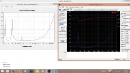
Secured the top on, without glue, to run a quick impedance sweep to see measured response vs predicted and play around with stuffing.
Have used two Ikea pillows for stuffing, where Bjorno suggested and will run some FR tests, when I can clear my exceptionally noisy 3 year old out of the house!
I presume the upper ripples in the measured impedance curve are due to leeks from the lack of glue between the top panel and the rest of the walls. What I don't understand is the much lower peak in the lower peak - abut 50ohm down on predicted - is this showing me something I have missed? The tuning trough is still around the 20hz mark, so that looks ok.
Any observations from these?
Attachments
Secured the top on, without glue, to run a quick impedance sweep to see measured response vs predicted and play around with stuffing.
Have used two Ikea pillows for stuffing, where Bjorno suggested and will run some FR tests, when I can clear my exceptionally noisy 3 year old out of the house!
I presume the upper ripples in the measured impedance curve are due to leeks from the lack of glue between the top panel and the rest of the walls. What I don't understand is the much lower peak in the lower peak - abut 50ohm down on predicted - is this showing me something I have missed? The tuning trough is still around the 20hz mark, so that looks ok.
Any observations from these?
Hi TheBaronGroog,
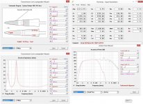
The lower Impedance Peak is probably due to too much Flow Resistance:
You should try to open up a free Air path from the rear of the Driver to the port especially if the rest of the entire volume is covered with Stuffing.
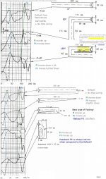
Try an empty CSA tunnel of at least Sd/3 or wider in size...An Example in Picture 1.
The lower Peak should be loaded no lower than about 14-15 Ohm.
The real location of the Impedance Peaks differs from what HR predicts: Bends are not covered in HR but your measured are correctly placed and where they should be. See the Picture 2.
b
Attachments
I presume the upper ripples in the measured impedance curve are due to leeks from the lack of glue between the top panel and the rest of the walls.
They could be due to panel flex if the cabinet is not properly braced. Rest something heavy like a sandbag on top of the enclosure and repeat the measurement to see if the ripples disappear.
Hi TheBaronGroog,
The lower Impedance Peak is probably due to too much Flow Resistance:
You should try to open up a free Air path from the rear of the Driver to the port especially if the rest of the entire volume is covered with Stuffing.
Try an empty CSA tunnel of at least Sd/3 or wider in size...An Example in Picture 1.
The lower Peak should be loaded no lower than about 14-15 Ohm.
The real location of the Impedance Peaks differs from what HR predicts: Bends are not covered in HR but your measured are correctly placed and where they should be. See the Picture 2.
b
They could be due to panel flex if the cabinet is not properly braced. Rest something heavy like a sandbag on top of the enclosure and repeat the measurement to see if the ripples disappear.
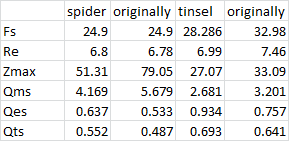
Thank you both, just tried some more testing and setting up with REW - glue between one driver's spider and former has come away and coil detached from tinsels - other driver isn't far behind! B!gger!
Will dig out the solder iron for the detached tinsel - any suggestions for glue to re-glue the spiders? Should have tested them more thoroughly before spending this long on an enclosure!
Oh,
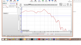
I did manage to measure the response with REW before the problem with the drivers fully revealed itself. They were crossed over at 14 and 60Hz 48dB/oct - the screenshot is after REW EQ applied to miniDSP but it didn't appear to change anything in terms of the output and curve looks the same!
I did manage to measure the response with REW before the problem with the drivers fully revealed itself. They were crossed over at 14 and 60Hz 48dB/oct - the screenshot is after REW EQ applied to miniDSP but it didn't appear to change anything in terms of the output and curve looks the same!
Attachments
I have managed to "save" them; the one with only a detached spider is fully working again - though haven't remeasured spec or FR to see how much my repair has changed response. The one with the broken tinsel has been repaired too, but I think I have inadvertently skewed the VC as noise is evident at higher volumes - though upon removal of the magnet I cannot see any evidence on the VC/former of rubbing so unsure what the issue is.. will remove the glue and try again - I've tried finding online guides, but not found anything suitable - any suggestions? Know of any youtube clips of failure modes - trying to workout what is causing the noise as cone appears to move freely when push in/out?
- Status
- This old topic is closed. If you want to reopen this topic, contact a moderator using the "Report Post" button.
- Home
- Loudspeakers
- Subwoofers
- 2x KEF B139 for home theatre challenge