@TheBaronGroog
the attachment was too small.you forgot to resize the canvas
I tried, this is what happened:

Attachments

Last edited:
I've had a bit more of a play, widened the port to 55mm, realise I will have to increase overall enclosure length to accommodate this.
Active BP crossover 20Hz-60Hz
I've also thrown together a sim for some Focal 6w2 midrange for some floor standers - will be using Dali Ikon Ribbon/Tweets with them and active crossovers.
Thoughts welcome!
Oh, and how do I model stuffing in HR? I can't find it anywhere - do I need a later version?
Hi,
 Diminishing return on the performance?
 Tried to show how to insert HR Stuffing..
b
Attachments
Tried to show how to insert HR Stuffing..
It's a bit easier using Version 34.70...
Attachments
It's a bit easier using Version 34.70...
Hi David,
Much easier!
I had to look back at:
http://www.diyaudio.com/forums/subwoofers/119854-hornresp-452.html#post3934884
to see what I've missed.

Thank You David! This update makes it even easier to find (Saving Time too) the right amount of 'Fiber-fill' to tame a Quarter-Wave Ripple infested Cabinet.
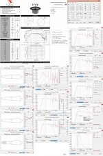
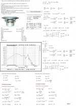
I tested to optimize an OD-TL design using a Peerless of India 4 Ohm Speaker Driver: A 10inch D25PV that have to operate in a Volume > 3x Vas thus when operated only would survive depending of a proper chosen LP filter and a Damping.
Products - PeerlessAudio.com
The first and second of Pictures: T/S and an OD-ML-TL example
b
Attachments
Thank You David!
Hi bjorno,
You're most welcome - I thought you might like the change
.I was a little surprised that you were not already using the latest version, as you are normally an "early adopter" of Hornresp updates
.Kind regards,
David
Hi,
Tried to show how to insert HR Stuffing..
b
From my re-models I shifted F3 up a little, but gained a flatter response overall, unless you mean the crossover?
Ok, found a little time for a play with HR, finally got it to update to 34.8.
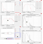
I've played with the port dimensions, crossover frequencies and added some stuffing in.
Will lower my HPF to 14Hz/24dB to keep bottom end and prevent over excursion, LPF I'm still happy with the 60Hz/24dB point - which brings me onto the stuffing; I've played around with it and "all" it seems to do is smooth the response above my intended pass band and reduce the output at the bottom end - am I missing something bigger here? I can certainly see how stuffing will help smooth the output of the Focal tower so will model that a lot more.
Believe it or not I'm being pressured to commence the build so any more input would be greatly appreciated by me and the Mrs!
Greg
Ok, found a little time for a play with HR, finally got it to update to 34.8.
I've played with the port dimensions, crossover frequencies and added some stuffing in.
Will lower my HPF to 14Hz/24dB to keep bottom end and prevent over excursion, LPF I'm still happy with the 60Hz/24dB point - which brings me onto the stuffing; I've played around with it and "all" it seems to do is smooth the response above my intended pass band and reduce the output at the bottom end - am I missing something bigger here?
SNIP......
Greg
IME a Tapered QWP or a straight QWP will have the response smoothed up above the passband (100-? Hz), with the addition of damping material, which at first seems unneccessary, but even with a steep XO the signal material at these frequencies is still audible to some extent.
It is just a juggling act between loss of efficiency and reduction of distortion at the top end.
I found that I prefer to lowpass the sub at 60 or 70 Hz maximum to help the situation.
Also, I prefer no more than 4th order LP @ 60-70 Hz and tend to like 3rd order response on the LP or else the phase is badly effected.
It only takes a little damping material in the 1st 1/3 of the distance between L1 and L2.
Dave
Last edited:
Ok, will bear that in mind when it comes to the build, thank you.
Anyone see any way of simplifying the design Oliver (tb46) gave in post 33? I find myself running round in circles over this design, I never have enough time to sit down and go through all the permutations so have to re-examine everything each time I come back to it - I'm close to just buying the wood and making something - lol!
Anyone see any way of simplifying the design Oliver (tb46) gave in post 33? I find myself running round in circles over this design, I never have enough time to sit down and go through all the permutations so have to re-examine everything each time I come back to it - I'm close to just buying the wood and making something - lol!
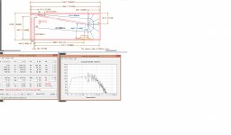
Sorry, but if it gets much simpler, it will be an empty box with a hole in it, so what specifically is 'messing with your mind'? I mean for building purposes, all you need to pay attention to is the dimensions that show its size and where to locate the internal boards that to keep it simple can be considered as full width braces placed at odd places and/or angles to the rectangular shaped outside walls. All the rest is just showing how the HR sim used to design it relates to it.
GM
GM
^lol
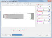
Basically - should I just keep to Oliver's original PDF of the box and just round over the port entry or go with my mod which increased the horn length, reduced S1 to 0.1 and saw the central divider extend down into the port mouth reducing the volume slightly but ridding myself of the stepped transition?
Basically - should I just keep to Oliver's original PDF of the box and just round over the port entry or go with my mod which increased the horn length, reduced S1 to 0.1 and saw the central divider extend down into the port mouth reducing the volume slightly but ridding myself of the stepped transition?
Attachments
This is what I get for responding to just a post Vs a whole thread........
When it comes to bass, efficiency trumps a flat response, complex design details due to the size WLs involved and Forest Gump's 'simple is as simple does' advice applies IME. Factor in that bjorno has already agreed in principle, go ahead and build it per your simplified layout.
GM
When it comes to bass, efficiency trumps a flat response, complex design details due to the size WLs involved and Forest Gump's 'simple is as simple does' advice applies IME. Factor in that bjorno has already agreed in principle, go ahead and build it per your simplified layout.
GM
Armed with 2 * B139s I am considering the same sub woofer application but for music only at this stage.
At the cost of added build complexity my thoughts are to split the design to give horizontally opposed drivers. Also this would provide additional internal bracing. With the box on it's side this means one driver would be on left and the other on right. Speaker would be centrally located on floor between main speakers. It would be under, but not in contact with, equipment rack.
Can I just divide widths by 2 and add a central divider? Does this approach make sense?
Yes, with the understanding that each 'cab' tuning will be off a little due to each having a different vent end correction than a single large one, though at low frequencies it shouldn't be audible. What may be audible though is if you use a > ~80-100 Hz XO point since the distance between the two drivers will be far enough to begin losing its mutual coupling at a much lower frequency.
GM
GM
Yes, my comments are only related to acoustical loading WRT separating the two. Now if you move them further apart, then at some point their mutual coupling drops enough for the drivers to become uncoupled. For instance, my speakers are ~12 ft apart, so only <50 Hz has any useful driver coupling, though still plenty through the vent's useful output BW that peaks at ~16 Hz.
GM
GM
- Status
- This old topic is closed. If you want to reopen this topic, contact a moderator using the "Report Post" button.
- Home
- Loudspeakers
- Subwoofers
- 2x KEF B139 for home theatre challenge