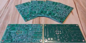
Using a self made double sided pcb here would be a big problem as you are not able to correctly solder some parts due to the missing plated-through holes. Maybe one starts a group buy for the pcb's....
But i think for me(beginner) use double side is dificullt.
...
")
Thx for info. Which setup version of ARTA have you installed?
Running wine 1.7.2 and ArtaSetup182.exe is also OK but not using wine 1.7.17
ARTA 1.8.2
Sorry for late reply...
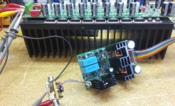
... works out of the box from first power on without any problems.
A quick THD+N test shows exactly same measurement results as lab sample.
That looks very nice, you are so quick in assembling that amp.
That looks very nice, you are so quick in assembling that amp.
Thanks! Attached the explanation why assembling seems to be so fast...
Attachments
...the transformer model isn't correct...
Better transformer simulation models are always welcome...
You built a nice amplifier in the time I took just to make some measurements for an improved model.
First I measured the primary inductance of a toroidal power transformer with a conventional inductance meter.
Result was similar to your measurement used in your model, about 1.3 H, far too low because there wasn't sufficient current to drive the core into the operational part of the hysteresis curve.
Then put a 100 VA toroidal on the mains and measured the no load current.
About 6 mA at 246 V (nominally 240 or 230 V)
So about 1.5 VA at no load, a believable number.
So primary inductance in actual operation is about 130 H.
The two measurements were made on different transformers but the factor of 100 is dramatic and obviously not due to the minor transformer differences.
Primary resistance measured by multimeter was 26 ohms.
So copper losses are a truly tiny contribution to standby power demand.
I haven't measured the real power consumption to determine iron losses yet.
I also measured the stray inductance with the inductance meter and came up with about 1 mH.
I expect this number is more accurate than the primary.
I should have measured secondary stray inductance, will do this soonish.
Best wishes
David
Last edited:
...
So primary inductance in actual operation is about 130 H.
...
Dear Dave,
how to measure my 650 VA toroids to get correct inductance values?
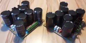
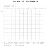
Attached the startup sequence of my new power supply with connected power amplifier (consumes about 500mA if idle). (osci screenshot: 20V/div and 100ms/div)
Used Toroid: 650VA / 230V / 2 x 50V
The voltage has been taken directly at network F1-C21-C1-D1 (schematic see post 1005). Maybe this helps to refine the simulation model.
Attachments
Last edited:
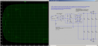
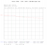
... zoomed to view diode switch ringing ...
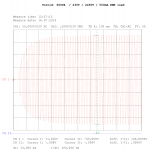
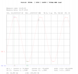
left picture: amplifier idle / ~ 500mA consumption
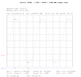
right picture: amplifier serving 200W RMS @8R (~ 2,5A consumption)
left picture: amplifier idle / ~ 500mA consumption
right picture: amplifier serving 200W RMS @8R (~ 2,5A consumption)
Attachments
Last edited:
...how to measure my 650 VA toroids to get correct inductance values?...
I know you are safety conscious, but in case anyone else reads this and decides to try it.
This is a 240 V circuit! Lethal! Use a current probe at least.
Measure the current in the primary with the transformer connected to the mains but no load at all on the secondary. That is, open circuited secondary, no capacitors, no diodes at all.
From that you can calculate the primary impedance and then inductance.
246 V / .006 A = 41 000 at 50 Hz (=314 radian/sec)
So 41 000 / 314 = 130 henry.
I am curious to see how it scales with transformer VA, I will check a few from a friend when we next meet.
Are C19 and C20 in your circuit to represent the distributed capacitance of the transformer secondarys?
I haven't measured this yet, it is an inconvenient measurement.
10 nF looks a bit excessive but the results are quite insensitive to this value so it doesn't matter much.
Best wishes
David.
Last edited:
Fine! One can never say often enough, that this voltages are lethal.I know you are safety conscious, but in case anyone else reads this and decides to try it.
This is a 240 V circuit! Lethal! Use a current probe at least.
...
Of course there may be many other dangerous situations like exploding capacitors or deadly-stressed bjt's sending out shrapnel to kill your eyes and so on...
No - EMI /RFI killer.Are C19 and C20 in your circuit to represent the distributed capacitance of the transformer secondarys?
...
Thx for maths: will measure my transformers.
Br, Toni
...
From that you can calculate the primary impedance and then inductance.
246 V / .006 A = 41 000 at 50 Hz (=314 radian/sec)
So 41 000 / 314 = 130 henry.
...
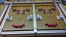
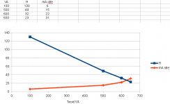
... used 0.1R in series with coil to measure mV rms.
Here are my measurement results (note: my mV rms meter isn't very exact so the results are preliminary!)
650VA: 23H
600VA: 32H
500VA: 49H
Has anyone results comparable to this one?
Attachments
Last edited:
now try measuring the primary current for various Mains supply voltages.
You will find that the primary current increases significantly as you approach the maximum usuable primary voltage.
When you convert that primary current to inductance you will find that inductance drops as saturation gets closer.
Watch out for transformers that enter the saturation region, at your maximum Mains supply voltage.
If any of your transformers fall into this saturation region, then adding a few dozen primary turns cures the problem. And makes the transformer run cooler and consumes less electricity.
We in the UK have adopted the "harmonised" EU mains supply voltage.
It is 216Vac to 253Vac.
The maximum voltage in the UK is supposed to be 253Vac, i.e. 230Vac +10%
BUT !!!!!
the previous standard was 240Vac +6% and that gives a maximum supply voltage of 254.4Vac
That extra 1.4Vac makes a difference when checking for near saturated transformers.
What is the maximum mains supply voltage on mainland Europe?
No - EMI /RFI killer.
The snubber capacitors should be at least 16 times the size of the parallel capacitance (yours plus stray distributed) if you want to kill the resonance completely. So increase the snubbers a little and/or decrease these.
As the ratio increases the optimum value of Rsnubber becomes less critical.
That is, the curve of resonance suppression versus Rsnubber develops a plateau rather than an optimum peak.
will measure my transformers.
Thanks for the measurements. More or less what I expected, will compare and see how much variation for similar size transformers.
What was the mains volts?
I don't have experimental data on this but I think Andrew is correct, it may be quite sensitive.
Best wishes
David
Last edited:
...
What is the maximum mains supply voltage on mainland Europe?
Afaik the same as yours - the new harmonized values.
During my measurements I have had 226V which is normal on 10:00 AM
Standard is here 230V.
It is EXTREMELY sensitive.now try measuring the primary current for various Mains supply voltages.
You will find that the primary current increases significantly as you approach the maximum usuable primary voltage.
When you convert that primary current to inductance you will find that inductance drops as saturation gets closer.
Watch out for transformers that enter the saturation region, at your maximum Mains supply voltage.
If any of your transformers fall into this saturation region, then adding a few dozen primary turns cures the problem. And makes the transformer run cooler and consumes less electricity.
I was once involved in sorting out an international commercial product that would blow mains fuses in certain countries. Malaysia was worst case. The cure was specifying a transformer with more primary turns.
As the transformer approaches saturation (ie the mains voltage rises), you'll see the no load current become VERY contaminated with odd harmonics as well as go through the roof.
I'm not sure an 'inductance' value has any meaning in this case.
________________
The 'inductance' of an iron cored inductor, including transformers varies a lot with level. I post a pic of frequency response measurements in a separate transformer thread .. I think on another forum
What does remain consistent is the 3rd harmonic distortion which scales with frequency and load & source resistance. This is my LF criteria when specifying audio transformers.
Last edited:
- Home
- Amplifiers
- Solid State
- 2stageEF high performance class AB power amp / 200W8R / 400W4R