


The Quasimodo shows that more damping (lower value resistor) is NOT a universal solution.Probably quite difficult to predict accurately, need to model capacitor stray inductance, ESR, trace inductance etc. etc.
But I expect very low level - and then suppressed more by the amplifier Power Supply Rejection Ratio, perhaps 60 dB and possibly quite a bit more.
So I am unconcerned by attempts to find the "optimum" snubber resistor.
Your approach looks fine, just damp it heavily........
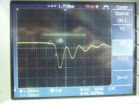
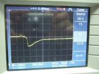
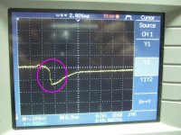
A large value resistor shows a lot of ripple.
A zero value resistor shows a lot of ripple.
Resistor values in between these two limits show less ripple.
The optimal value resistor shows least ripple.
Going any lower than optimal, increases the ripple !
Last edited:
use an air core !As always: Thx!
Now its clear that using an inductor to reduce the ripple voltage here is more or less nonsense compared to the effect and price of 2 pieces 0.47R resistors ...
Is there anybody out there needing some pieces of FT140-77 cores?")
It has resistance given for free and the inductance improves on what attenuation is available from that resistance alone.
Look at the way the saw tooth "shape" changes as you increase the inductance.
Air core with a large spread magnetic flux... not too good for small signals. In my opinion it is too risky bussines. In any way, the coil will working for higher frequencyes than 50-60hz and the resistor will be verry effective too in that band.
For snubbers the things wich does matter it is a value of the capacitor , the value wich establish the resonant frequency of the equivalent circuit wich now include the snubber and the value of the resistor wich establish the damping factor. The resonant circuit it is formed by a parasitic capacitance and the leakage inductance of the transformer. A snubber with 100nF+100R it is almost perfect for all types of transformers.
For snubbers the things wich does matter it is a value of the capacitor , the value wich establish the resonant frequency of the equivalent circuit wich now include the snubber and the value of the resistor wich establish the damping factor. The resonant circuit it is formed by a parasitic capacitance and the leakage inductance of the transformer. A snubber with 100nF+100R it is almost perfect for all types of transformers.
A snubber with 100nF+100r may just about do for many transformers and not cause too much harm.................. A snubber with 100nF+100R it is almost perfect for all types of transformers.
As for "perfect" ?
There is no way that you can show that 100nF+100r is "perfect" !!!!
Toroidal transformer 350 VA , 2x40Vac secondary. I have two transformers. Each transformer has a 50A bridge rectifier. I was trying for a 4 different various transformers and a snubber like 100nF+100r working very fine. The problem isn't too tight, there is a large blade of capacitor values, somewhere between 10nF and 1uF but then u must change the resistor value. Again, the problem it is not the bridge rectifier, the problem consist in the LC resonance of the parasitic components of the transformer. The bridge rectifier it is only the ignition part, u don't need to cure here, so u dont need to buying an expensive bridge rectifier.
The capacitor swamps the capacitance in the resonance, so it effectively determines the resonant frequency and characteristic impedance of the resonance. So you can use a small cap and larger resistor. I prefer to use a large cap and small resistor because it shifts the resonant frequency very low and acts as a better shunt filter after the transformer for line noise. It also loads the transformer slghtly when the rectifiers aren't conducting, which reduces saturation in some transformers. And of course, it absorbs more of the rectifier noise so it isn't radiated by the transformer.
Of course you can't make it too large or your resistor will get hot, and if it's already hot, then it won't stand a chance against line surges or inrush.
But if your only concern is the ringing on the secondary, then a small cap and resistor will work.
Of course you can't make it too large or your resistor will get hot, and if it's already hot, then it won't stand a chance against line surges or inrush.
But if your only concern is the ringing on the secondary, then a small cap and resistor will work.
I would say 3.3uF and up. Not something that would be too inductive. MKT is small enough to not be very inductive.
The survival of the resistor is a complex issue. At 60Hz, the cap blocks most of the current so ideally, the resistor almost doesn't get hot. But the current through the resistor increases proportionally to the frequency. The first problem is the distortion of the signal waveform caused by the rectifiers - the cap will absorb this and those HF currents can dissipate a surprising amount of power in the resistor. Assuming that is okay, then you have problems with the turn-on transient, which the resistor needs to be able to handle (carbon comp resistors have good surge tolerance). And then there are also line transients whenever your AC or blender or garbage disposer turns on.
The danger the resistor is in depends on voltage, capacitance, load, trafo performance, etc. I think the best way to understand it is to simulate it, because it will be different for each application. Yes, you can just use a power resistor, but it may be inductive and I don't like having useless heaters in my designs.
That said, I used values of 15R-30R in a trimmer and I eventually discovered the trimmer had failed and gone open - it had never been warm, must have been a transient. I would suggest using a trimmer to find the right value and then substituting a carbon comp resistor of 500mW.
The Quasimodo shows that ...lower value resistor... is NOT a universal solution.
Thank you for the comments, they have made me clarify the issue.
There a difference between "damp it heavily", as I wrote, and "lower value resistor".
I haven't read the "Quasimodo" thread extensively but it seems to reference an article about "Optimum Snubbers" that misses a few points.
In particular the OS article does not much consider the implications of the value of the capacitor in series with the snubber resistor.
That capacitor is the reason the behaviour is not monotonic.
AFAIK the Quasimodo varies the resistor for a particular capacitor.
Whereas Keantoken's analysis of this factor is perceptive.
As the capacitor is increased then the optimum snubber resistor value decreases.
You can damp it as much as you want, you don't need to critically damp it.
At the cost of extra power dissipation, of course.
I haven't yet read the article in Linear Audio v5 by M Jones about this.
Does he cover this?
Best wishes
David
Last edited:
I would say 3.3uF and up. Not something that would be too inductive. MKT is small enough to not be very inductive.
The survival of the resistor is a complex issue. At 60Hz, the cap blocks most of the current so ideally, the resistor almost doesn't get hot. But the current through the resistor increases proportionally to the frequency. The first problem is the distortion of the signal waveform caused by the rectifiers - the cap will absorb this and those HF currents can dissipate a surprising amount of power in the resistor. Assuming that is okay, then you have problems with the turn-on transient, which the resistor needs to be able to handle (carbon comp resistors have good surge tolerance). And then there are also line transients whenever your AC or blender or garbage disposer turns on.
The danger the resistor is in depends on voltage, capacitance, load, trafo performance, etc. I think the best way to understand it is to simulate it, because it will be different for each application. Yes, you can just use a power resistor, but it may be inductive and I don't like having useless heaters in my designs.
That said, I used values of 15R-30R in a trimmer and I eventually discovered the trimmer had failed and gone open - it had never been warm, must have been a transient. I would suggest using a trimmer to find the right value and then substituting a carbon comp resistor of 500mW.
Thank you for the tips. I had a presumption about "large cap" around 10uF and you confirm this. I've been thinking to round the rectifier edge with a 10uF but to be honest I feared to do this. Sometimes we are blocked in a classic ways of thinking...
Attachments
HI, group buys for this amplifier?
thanks
Everybody is allowed to start a group buy as long as it is non commercial.
BR, Toni
...
I haven't yet read the article in Linear Audio v5 by M Jones about this.
Does he cover this?
Best wishes
David
IMHO: The interesting article doesn' t take into account, that a secondary output paralleled capacitor (which in my opinion is necessary to kill EMI/RFI coming from primary side or air) heavily reduces the frequency of the oscillation hence the resulting snubber combination increases in capacitance size and decreases resistor values.
Also removing diode paralleled small capacitors (or snubbers) would make it possible to radiate HF due to diode switching. Diode switching HF is of course depending on the parts used. So in many designs you may remove the 4 pieces small capacitors as long as there is the "new" C//RC diode bridge input filter installed.
Schematics and pcb gerber files are free to use only for non commercial DIY projects.
verry nice project and thanks for sharing sir Toni...
Interested,,
this is dual layer pcb right?
... a secondary output paralleled capacitor...heavily reduces the frequency of the oscillation hence the resulting snubber combination increases in capacitance size and decreases resistor values...
Exactly.
If the article doesn't consider this then it is incomplete.
I have an analysis of this that I am pleased with because it is simple and intuitive but effective - better snubbers with less maths and no extra test equipment.
I hope Jan Didden wants an article. At least a brief one
Best wishes
David
Last edited:
You are welcome!verry nice project and thanks for sharing sir Toni...
Interested,,
this is dual layer pcb right?
- input/vas and bias/output pcb's are doublesided.
- power supply pcb is single sided.
Toni
You are welcome!
Have Fun,
- input/vas and bias/output pcb's are doublesided.
- power supply pcb is single sided.
Toni
Thank you sir for your confirmation,
But i think for me(beginner) use double side is dificullt.
Regards,
Boedy
- Home
- Amplifiers
- Solid State
- 2stageEF high performance class AB power amp / 200W8R / 400W4R