Not really off topic - MOSFET VAS variant simulation
Have fun, Toni")
- during lab cleanup I found a couple of IRF9610 lying around from an old papa Pass project
- found an IRF9610 spice file
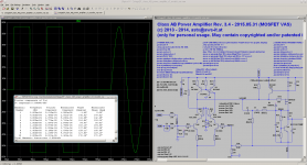
- simulated SA2013 v3.4 using IRF9610 for VAS
Have fun, Toni
Attachments
After Reading through This thread i have a few comments.
It is true that In some cases a single output pair would perform better than Multiple output pairs. But In most cases designers adds extra pairs without changing the driverstage. This is a major fault!! Redesign the AMP to drive the extra pairs well and it will not be a problem .
Secondly doing a 150watt into 8r with only one pair of 250watt devices is a risky business .
I would say use several pairs at that point to keep peak power Below 30 to 50% of max power available through devices, thermal interface and heatsink .
If you run devices close to max current they get unlinear.
Sent from my iPhone using Tapatalk
Attached are the results. NFB gain at 20 kHz drops from 60db to 42db compared to enhanced VAS. Maybe I will try this variant the next days in real life. Hopefully the mosfet spice file is not too far away from reality.
- during lab cleanup I found a couple of IRF9610 lying around from an old papa Pass project
- found an IRF9610 spice file
- simulated SA2013 v3.4 using IRF9610 for VAS
Have fun, Toni
Can you share the IRF9610 spice model?
... is embedded in the asc file.Can you share the IRF9610 spice model?
1pr of 250W devices gives a 500W output stage............................Secondly doing a 150watt into 8r with only one pair of 250watt devices is a risky business .
I would say use several pairs at that point to keep peak power Below 30 to 50% of max power available through devices, thermal interface and heatsink ..................
30% of that is 150W, 50% of that is 250W
What did you mean to say when you gave us that guidance?
With an +/-60VDC supply and 150W into 8R you will have around 4.3Arms => 260W. That is an pure resistive load.
260W into an 0.4K/W heatsink is 103K. An 250W device have an Junction to case of 0.5K/W. => So this will generate 125Watt/device x 0.5K/W => 62.5K.
Max temperature is 150 degrees celcius. We are now at 165.5K + room temperature.
3 pairs of 250Watt devices will mean 43.3Watt per device -> 21.6K per device meaning 125K + room temperature....
Do you get the picture?
So an amp producing 150Watt into 8R needs an good heatsink of below 0.4W and more than 3 pairs of 250W output devices as possible. If anyone
Then there is the crest factor which is normally set to ~20%. So an amp delivering 300Watt into 4R with 3 pairs , 0.4Watt heatsink and +/-60Vdc supply will produce something like 105W with music signal.
42K (heatsink) + 9K (Per transistor) + 9K (Thermal interface) = 60K + room temperature 25 - 50degrees (Depending where you live and how crowded there is around the amplifier)
So with an room temperature of 25 degrees there will be a margin of 65 degrees.
With one pair it will leave 3 degrees to the room temperature. That is going to fail!
Please can you share the attenuation adapter schematic?attached IMD measurement and picture of test setup. Idle current - mostly bias is about 0.5A as you can see in the background.
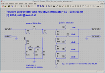
Home brew attenuation adapter as seen in the foreground is attached to ASUS Xonar sound cards line input. The 100W measurement has been done with 20dB attenuation, the 200W with 40dB attenuation using a simple jumper. Not very comfortable but cheap and it works.
Now I need to rework SA2013 pcb's to reflect v3.4 changes.
- 0.00052% @ 100W @ 8R
- 0.00079% @ 200W @ 8R
Regards.
Originally Posted by sonnya View Post
...........................Secondly doing a 150watt into 8r with only one pair of 250watt devices is a risky business .
I would say use several pairs at that point to keep peak power Below 30 to 50% of max power available through devices, thermal interface and heatsink ..................
1pr of 250W devices gives a 500W output stage.
30% of that is 150W, 50% of that is 250W
What did you mean to say when you gave us that guidance?
I recognise what you want to say. I agree with you in principle, but your initial explanation was incomprehensible to me. The long explanation is still incomprehensible to me. Maybe that is my fault.With an +/-60VDC supply and 150W into 8R you will have around 4.3Arms => 260W. That is an pure resistive load.
260W into an 0.4K/W heatsink is 103K. An 250W device have an Junction to case of 0.5K/W. => So this will generate 125Watt/device x 0.5K/W => 62.5K.
Max temperature is 150 degrees celcius. We are now at 165.5K + room temperature.
3 pairs of 250Watt devices will mean 43.3Watt per device -> 21.6K per device meaning 125K + room temperature....
Do you get the picture?
So an amp producing 150Watt into 8R needs an good heatsink of below 0.4W and more than 3 pairs of 250W output devices as possible. If anyone
Then there is the crest factor which is normally set to ~20%. So an amp delivering 300Watt into 4R with 3 pairs , 0.4Watt heatsink and +/-60Vdc supply will produce something like 105W with music signal.
42K (heatsink) + 9K (Per transistor) + 9K (Thermal interface) = 60K + room temperature 25 - 50degrees (Depending where you live and how crowded there is around the amplifier)
So with an room temperature of 25 degrees there will be a margin of 65 degrees.
With one pair it will leave 3 degrees to the room temperature. That is going to fail!
I propose that this is far simpler:
The maximum output of a BJT ClassAB amplifier is around 1/5th to 1/6th of the total Pmax of the devices in the output stage.
i.e. one pair of 250W devices amounts to a total Pmax of 500W.
That gives a range of maximum output power of approximately 80W (500/6) to 100W (500/5).
Last edited:
Here we are.Please can you share the attenuation adapter schematic?
Regards.
Note: there is no protection for your soundcard. A better solution is to build the measure box as can be found on ARTA homepage.
Attachments
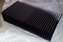
Heatsink ...
... this one will be used for SA2013 - 2 channels mounted per heatsink as SA2013 v3.4 will be a 4 channel amplifier driven by active crossover.
Heatsink dimensions: 400x210x86 mm, < 0.15RthK(K/W)
Datasheet: ct-540 from cooltec
... this one will be used for SA2013 - 2 channels mounted per heatsink as SA2013 v3.4 will be a 4 channel amplifier driven by active crossover.
Heatsink dimensions: 400x210x86 mm, < 0.15RthK(K/W)
Datasheet: ct-540 from cooltec
Attachments
Thanks .Here we are.
Note: there is no protection for your soundcard. A better solution is to build the measure box as can be found on ARTA homepage.
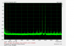
CCIF IMD is only DFD2 (see ARTA manual page 45/46)attached IMD measurement and picture of test setup. Idle current - mostly bias is about 0.5A as you can see in the background.
Home brew attenuation adapter as seen in the foreground is attached to ASUS Xonar sound cards line input. The 100W measurement has been done with 20dB attenuation, the 200W with 40dB attenuation using a simple jumper. Not very comfortable but cheap and it works.
Now I need to rework SA2013 pcb's to reflect v3.4 changes.
- 0.00052% @ 100W @ 8R
- 0.00079% @ 200W @ 8R
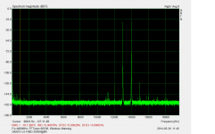
- 0.00021% @ 100W @ 8R
- 0.00028% @ 200W @ 8R
Attachments
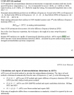
CCIF IMD is only DFD2 (see ARTA manual page 45/46)
Literally the excerpt does read that way.
But I suspect it is not true that the actual specification is only DFD2.
Instead, that some CCIF type instruments only measure DFD2.
Anyone have a copy of the standard to check?
Even DFD3 is very low (frequency products directly left and right from f1 and f2). Of course they may not be heard as good as DFD2 due to masking effects...
DFD3 will be well masked by the particular CCIF frequencies, but not by real music.
So I think the DFD3 is like 20 kHz 2nd harmonic distortion test. Still a reasonable test of linearity even if the specific measured frequency is inaudible.
You need not care because in your amp they are all inaudible
Best wishes
David
I notice that CCIF specifically recommends 19 + 20 kHz for amplifiers but you have chosen lower.
I expect you have a reason that is not just to improve the numbers?
Last edited:
The reason is the 48kHz sampling rate where generated 13/14k sinus has more as only 2 sampling points....
I notice that CCIF specifically recommends 19 + 20 kHz for amplifiers but you have chosen lower.
I expect you have a reason that is not just to improve the numbers?
The reason is the 48kHz sampling rate where generated 13/14k sinus has more as only 2 sampling points.
You mentioned you had an ASUS Xonar. I don't know all the different models but I think they do at least 92 kHz sample rate?
Best wishes
David
In Stereophile Magazine , John Atkinson talks in a first time about f2-f1 product , 1khz in 19+20 khz case, because it is in audio band and it is far away from test frequencys. Obviously the best is to have all the products small. Astx made a very good amplifier, almost perfect.
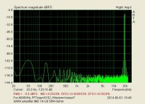
I repeat the measurement at SARA, my amplifier, at half of power, 50W in 8 ohm and DFD2 is 0.00005 %....Of course DFD3 is much bigger, but nobody is perfect
Good job, well done Astx, go on.
I repeat the measurement at SARA, my amplifier, at half of power, 50W in 8 ohm and DFD2 is 0.00005 %....Of course DFD3 is much bigger, but nobody is perfect
Good job, well done Astx, go on.
Attachments
Thanks!In Stereophile Magazine , John Atkinson talks in a first time about f2-f1 product , 1khz in 19+20 khz case, because it is in audio band and it is far away from test frequencys. Obviously the best is to have all the products small. Astx made a very good amplifier, almost perfect.
I repeat the measurement at SARA, my amplifier, at half of power, 50W in 8 ohm and DFD2 is 0.00005 %....Of course DFD3 is much bigger, but nobody is perfect
Good job, well done Astx, go on.
DFD2 of SARA looks really excellent - but why is DFD3 so much higher? Try to repeat your measurements with linear frequency scale and an averaging of about 8 to 16 times...
Same again as loopback reference to be sure, DFD3 does not come from soundcard.
Yes my Xonar can do 96k/192k. But noise level is higher choosing 96k and even higher using 192k.You mentioned you had an ASUS Xonar. I don't know all the different models but I think they do at least 92 kHz sample rate?
Best wishes
David

Need a better soundcard ...
- Home
- Amplifiers
- Solid State
- 2stageEF high performance class AB power amp / 200W8R / 400W4R