I've come a cropper trying less than 100n for the 'conventional' Zobel. My experiments were for precisely your reasons. 10R seems to be OK.
Were these just experiments with a real amp or did you simulate and check return ratio of both inner and outer loops?
Accurate simulation should be able to predict Zobel requirements but I have seen little written about this. Mostly it seems trial and error rules.
What IS useful, from sims, some Jurassic analysis & loadsa 'real life' is a smaller resistor in parallel with the Inductor ... say 4R7
Makes sense. I have never really checked this because I like a smaller resistor anyway, to make the traditional 2uF + 8R square-wave test look nicer(even if it is fairly irrelevant).
Best wishes
David
Some simple sims have shown that with dominant pole compensation the overall effect of different zobels is minimal. You get small changes in PM / GM but strangely with smaller zobels stability into capacitive loads appears reduced.
My simple mind is coming to the conclusion that for dominant pole as long as you are not running crazy slew rates there is no reason not to go for the 100n + 10R combo.
Please correct me if I'm talking rubbish.")
My simple mind is coming to the conclusion that for dominant pole as long as you are not running crazy slew rates there is no reason not to go for the 100n + 10R combo.
Please correct me if I'm talking rubbish.
I am not at all sure, but I am thinking that the nominal Zobel values of 10r + 100nF specifically suit 8ohms rated amplifiers.
I have a feeling that has developed only recently that the Zobel values should more correctly track the "rated" amplifier load impedance.
i.e. a preamp for driving a high load impedance would use >>10r and <<100nF
A power amp for driving 2ohms speaker would use <<10r and >>100nF
I have a feeling that has developed only recently that the Zobel values should more correctly track the "rated" amplifier load impedance.
i.e. a preamp for driving a high load impedance would use >>10r and <<100nF
A power amp for driving 2ohms speaker would use <<10r and >>100nF
Some simple sims have shown that with dominant pole compensation the overall effect of different zobels is minimal.
Sounds reasonable to me.
Even with a more complex, closer approximation to Bode maximum feedback, the sensitivity to different Zobel values is fairly low.
Best wishes
David
I've come a cropper trying less than 100n for the 'conventional' Zobel. My experiments were for precisely your reasons. 10R seems to be OK.
This was in the course of the development of a commercial amp in the early 80's. Like you, I hoped the Zobel could introduce a pole & zero, with the zero in a useful place but always ended up with sorta 100n + 10R .. both in sim & in real lifeWere these just experiments with a real amp or did you simulate and check return ratio of both inner and outer loops?
Accurate simulation should be able to predict Zobel requirements but I have seen little written about this. Mostly it seems trial and error rules.
It was one of the reasons I wrote my own DOS linear circuit analysis package cos I found algebraic analysis too error prone for wun hu kunt reed en rite. It was(is) no way as sophisticated and easy to use as LTspice. I spent a lot of time converting SPICE models to my simplified models.
What DID emerge from that exercise was the usefulness of using a smaller resistor in parallel with the inductor.
The definitive stability criteria are described in
http://www.diyaudio.com/forums/solid-state/235188-tpc-vs-tmc-vs-pure-cherry.html and
http://www.diyaudio.com/forums/analog-line-level/218373-discrete-opamp-open-design-231.html#post3266142
In essence, my LTspice efforts tend to replicate these 'real life' tests in SPICE world.
__________________
From that exercise, I also concluded that I couldn't design a 1ppzillion amp without some L/R network in series.
This was of great importance to me as I'm really a speaker man. The series L/R makes speaker measurements dependent on the amp.I know of only 2 commercial amps which are unconditionally stable with different loads but neither are 1ppzillion. We kept some of these working for decades for use in factory & lab test.
__________________
AndrewT, Zobels have very little to do with "rated amplifier impedance".
The important issue it deals with is unconditional stability with different load. The difficult loads are usually very far from nominal but are certainly found in 'real life' speakers.
Last edited:
Sounds reasonable to me.
Even with a more complex, closer approximation to Bode maximum feedback, the sensitivity to different Zobel values is fairly low.
Best wishes
David
Suppose you have to take into account the amp output impedance at the frequency where the zobel starts to load significantly?
So, it comes down to in my limited mind and understanding:
1) Making sure that the amp is stable while unloaded.
2) Power dissipation during fast transients / clipping.
3) Swamping the "parasitics"
4) Helping with RFI ingress.
So taking notice of yourself, kgrlee and the sims. the common values of 10R + 100n seem the way to go. Except that making them distributed seems to bring some benefits. Ability to use smaller components that will have better HF properties and minimising parasitic inductance.
Paul
... some measurements added ... this one (v3.4) will be built
Have you tried simming an additional resistor from the junction of C1 and C2 (TMC caps) to ground or power rail? You can fine tune the square wave response this way and maybe reduce THD a little. Works for CFA style amps maybe it'll work for you.
Suppose you have to take into account the amp output impedance at the frequency where the zobel starts to load...?
Hmm, you could probably do it that way but that's not the way I look at it.
HERE is a link that shows Bode Maximum Feedback as the first plot.
Clearly, if that very specific curve is wobbled around by unforeseen load variations then the carefully worked out phase response will be deteriorated.
So I look at the Return Ratio plots as I try different loads and Zobels.
Should then do some TRAN simulations to check of course, because the RR plots are only linearised about the quiescent operational point.
But if there is reasonable PM and GM at quiescent and the amp is smart then it should stay stable over the normal operational conditions.
1) Making sure that the amp is stable while unloaded.
2) Power dissipation during fast transients / clipping.
Stability while clipped and just after is important too, often the worst case test for TPC/TMC and similar advanced amps.
Personally I don't care as much about this because I have super efficient speakers but it is essential for a production product, hence Richard Lee's emphasis on this from his commercial experience.
3) Swamping the "parasitics"
4) Helping with RFI ingress.
RFI is really a separate issue, just happens to be fixed by the same sort of network.
So taking notice of yourself, kgrlee and the sims. the common values of 10R + 100n seem the way to go. Except that making them distributed seems to bring some benefits. Ability to use smaller components that will have better HF properties and minimising parasitic inductance.
As already noted, I like Bob Cordell's idea of both a distributed Zobel and a second "Zobel" that is more about RFI input protection.
Except I put the Zobel "upstream" of the emitter resistors for even lower inductance.
Best wishes
David
Last edited:
A mixture of TMC and TPC? Do you have a reference / link to this CFA project?Have you tried simming an additional resistor from the junction of C1 and C2 (TMC caps) to ground or power rail? You can fine tune the square wave response this way and maybe reduce THD a little. Works for CFA style amps maybe it'll work for you.
Thx, Toni
Thanks to you and of course many thanks to all contributors too!Really nice to see this amp growing.
Carefull optimizations step by step.
BTW: hard waiting for the first prototype of your new class D project
BR, Toni
Me too. The current amplifier SA2013 v3.4 is using this variant....
As already noted, I like Bob Cordell's idea of both a distributed Zobel and a second "Zobel" that is more about RFI input protection.
...
A mixture of TMC and TPC? Do you have a reference / link to this CFA project?
Thx, Toni
Yes, effectively a mixture...
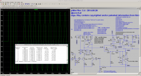
Here is a link to the schematic of the last working prototype. Eventually got rid of the lead compensation across the feedback resistor. Found it was better to tune the TMC/TPC comp.
http://www.diyaudio.com/forums/solid-state/246700-random-amp-questions-2.html#post3810586
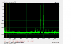
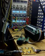
IMD SA2013 v3.4
attached IMD measurement and picture of test setup. Idle current - mostly bias is about 0.5A as you can see in the background.
Home brew attenuation adapter as seen in the foreground is attached to ASUS Xonar sound cards line input. The 100W measurement has been done with 20dB attenuation, the 200W with 40dB attenuation using a simple jumper. Not very comfortable but cheap and it works.
- 0.00052% @ 100W @ 8R
- 0.00079% @ 200W @ 8R
Attachments
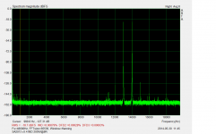
Noise ...
Output noise levels with input shorted via VP7723D (600R):
20 µV - A-weighted
39µV - BW 20kHz
54µV - BW 80kHz
117µV - Full bandwidth (~ 500kHz limit of VP-7723)
SNR in reference to 1kHz@200W@8R output level:
> 125 db - A-weighted
> 121 db - BW 20kHz
> 117 db - BW 80kHz
> 111 db - Full bandwidth (~ 500kHz limit of VP-7723)
... nearly the same values as SA2013 v3.1
0.039mVac over the audio bandwidth giving -121dB are good figures.
About 8.8nV/rootHz equivalent input noise (Ein).
simulation showed at output 140nV/rtHz which is about 4,8nV/rtHz Ein.Of course I will do.Repeat the measurements after all the components are inside of chassis.
The previously finished amplifier (v2 - see first post for an index) showed the same performance as the lab prototype.
- Home
- Amplifiers
- Solid State
- 2stageEF high performance class AB power amp / 200W8R / 400W4R