LTspice isn't telling the whole truth but is so...oo close.
I now need to force the SPICE model of the simple Cherry modified circuit to show these faults if this research is to go forward.
OK, As posted above I am now convinced that "pure Cherry" is non-optimal.
But the journey has been educational so let's see if we can improve the models even more.
TR of the VAS is fixed but there's about 40 more parameters per transistor variety.
What's the problem?
Best wishes
David
OK, As posted above I am now convinced that "pure Cherry" is non-optimal.
 sob sob
I'm now seriously challenged
The problem is what I posted in #484/487 is supposed to reflect 'real life' as measured by Toni in #492.But the journey has been educational so let's see if we can improve the models even more.
TR of the VAS is fixed but there's about 40 more parameters per transistor variety.
What's the problem?
It makes pseudo all my pontificating to Matze in #490
There's stuff which can be made more accurate before we do work on models.
The 'Baxandall pair' VAS version which I posted & then removed has almost exactly the faults that Toni shows in #492. I'm debating whether the 'cures' would be applicable too. Need to do more work.
_______________________
Toni, how do you do the PM & GM in #491? Is that with the Tian probe a the output as in #457?
How long is the ribbon cable in the pics of $492? I know you don't think it makes much difference.
As I don't have a 'real life' version to play with, to do this, I need the model to reflect 'real life'. I'm trying to correct everything which I know makes some difference.cherry compensation variant needs some rework to get the amplifier stable...
Unless you can lend me some of your prototypes .. Austria is near Australia isn't it?
With compensation up to the limit, 100n caps at the rails will cause an amp to oscillate because their resonance changes global phase. 1u+1R snubbers across the rails help with this. These snubbers should go across the OPS rails, because the outputs are the main leakage point for rail resonances.
What is the frequency of the oscillation? This will help us understand the cause.
When you increase or decrease the driver bias, does the oscillation last for a longer or shorter time? This will tell us whether driver recovery is a factor in oscillation. If not, it could be TIS recovery.
The outputstage has not been modified. So if your theory would be correct, why is it not possible to trigger this kind of oscillation with Miller, TPC or TMC compensation?
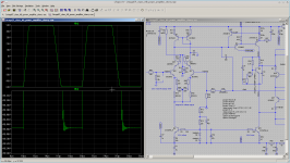
Yes to all that. I was using the 10n just to limit BW to 100kHz for the sim.
In real life, the worse case condition I would allow for in a simple amp would be a 10k pot so 2k5 source R at -6dB setting.
I'm partial to even higher order i/p BW limiting like Edmond shows in his 'Super TIS' page. My ideal is a BBC/IBA 1980's spec which requires at least 3rd order Bessel to achieve. But this is all extra bits so you might as well have the balanced i/p stage too.
The plan is to connect the amplifiers input to an active crossover output stage with low output impedance (< 600R). BW limit is mainly controlled by 150R/4.7nF input RC filter (~225kHz).
wonky Cherry stability
Toni, I don't think this will cure the wonky instability on Square waves but should help. Try the following. You have to do them all
I don't think the smaller PM & GM are causing the problem but the 'cure' for that is bigger C10 at the CM & C1, the Cherry capacitor. Maybe 100p. I've only done cursory sims of this particular change.
_____________________
Toni, I don't think this will cure the wonky instability on Square waves but should help. Try the following. You have to do them all
- C11 (collectors of Q7/10) to 10n
- C8 (across C8) to 10n
- remove C16 across R17 33
- decoupling across R22 VAS emitter resistor becomes 330p+1R
I don't think the smaller PM & GM are causing the problem but the 'cure' for that is bigger C10 at the CM & C1, the Cherry capacitor. Maybe 100p. I've only done cursory sims of this particular change.
_____________________
Though all versions have very high slew, >80V/us, this is only good for about 100kHz BW because it is a big 200W 8R amp. Otherwise it will slew limit with stupid input.The plan is to connect the amplifiers input to an active crossover output stage with low output impedance (< 600R). BW limit is mainly controlled by 150R/4.7nF input RC filter (~225kHz).
Last edited:
...
Toni, how do you do the PM & GM in #491? Is that with the Tian probe a the output as in #457?
How long is the ribbon cable in the pics of $492? I know you don't think it makes much difference.
As I don't have a 'real life' version to play with, to do this, I need the model to reflect 'real life'. I'm trying to correct everything which I know makes some difference.
Unless you can lend me some of your prototypes .. Austria is near Australia isn't it?
Dear kgrlee,
PM/GM check is done via Tianprobe() like #457. Btw. disabling output zobels worsens PM to 27 degree and GM to 14dB
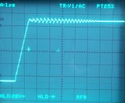
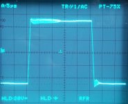
On simulating your cherry variant I have detected some kind of instability during square wave analysis - see attached picture.
I think the ribbon cable is not the problem but I will retest the cherry variant more in detail
- using different ribbon cables
- to find out the frequency of oscillation figure
If you want I can send you rev.1 PCB's for lab testing as Australia is not so far away from Austria.
Send me a pm with destination address if you would like to have ...
BR, Toni
Attachments
The outputstage has not been modified. So if your theory would be correct, why is it not possible to trigger this kind of oscillation with Miller, TPC or TMC compensation?
The stability compensation affects each aspect of the amp individually. Different compensation schemes react differently to driver recovery, VAS recovery and so on. Some have adequate phase margin normally but if anything ever saturates, the amp will explode into oscillation and burn a hole through the floor.
Another thing that would help is to look at small-signal square waves with minimal BW limiting on the amp. This will tell us whether Cherry is undersized or whether it is only having difficulties at the extremes.
BW limit on input during testing is defined by 150R/500p - 2.1MHz
The two square wave pictures from post #492 http://www.diyaudio.com/forums/soli...b-power-amp-200w8r-400w4r-10.html#post3534876 are taken at different output levels - do we need some more level steps?
Thanks for this Toni. I simulate with your 2nd Zobel disconnected to try & get worst case stability. I'm seeing the instability too when I look at V(outa) with different loads. That's how I came up with the recommendations in my previous post.PM/GM check is done via Tianprobe() like #457. Btw. disabling output zobels worsens PM to 27 degree and GM to 14dB
On simulating your cherry variant I have detected some kind of instability during square wave analysis - see attached picture.
I just want to know how long it is. Remember I'm trying to make the Sim replicate 'real life'. But if you can try the changes to the speedup/suckout caps & VAS emitter decoupling ...I think the ribbon cable is not the problem but I will retest the cherry variant more in detail
Thanks for the offer Toni but I'm a REAL beach bum in a place with more crocodiles than people.If you want I can send you rev.1 PCB's for lab testing
Send me a pm with destination address if you would like to have ...
Tomorrow I'm going to try and buy a broken 2x300W 4R Public Address Amp for the parts. If I succeed, I may take you up on it.I knew it! I heard Wiener Sangerknaben sing Mass at Sydney Opera House every second Sunday... as Australia is not so far away from Austria.
Alas Cooktown is nearly 3,000 km away. ________________
Kean, when an amp slew rate limits, it is overloaded. You can check this by plotting V(inp+)-V(inp-) of the LTP. All the square wave plots that Toni has posted (both for TMC & 'pure Cherry') show slew rate limiting. Essentially (2MHz BW) 20kHz square is like clipping the amp. so we are actually doing an 'overload' test.
When we get it as good as we can, no funny oscillations etc. we put back 100kHz input limiter to make sure the amp never slews until it clips.
Last edited:
...
Thanks for the offer Toni but I'm a REAL beach bum in a place with more crocodiles than people.
...
OT: which sort of "beach bum" as I am not a native english speaker ...
Urban Dictionary: beach bum
1, 2 (1-5), or 3 ?BR, Toni
When an amp with specific IPS, VAS and OPS has its compensation altered then any reduction in distortion is the result of increased feedback.
This is a platitude. It may be true, but it's so abstract and deceptive. Sure, but how do we get from point A to point B? Then comes more abstruse stuff that most would rather just shove off. I have a potentially more straightforward approach:
Any reduction in distortion is the result of decreased loading or leakage from loaded stages.
Compensation for us is by far a source of leakage, and secondarily a source of loading. TMC and TPC swap roles in dealing with either kind in different stages. TIS degeneration decoupling takes advantage of output stage parasitics to make Cherry compensation feasible; thus parasitics must be very carefully managed. With Cherry compensation there is less leakage of distortion than both TMC or TPC, so IPS loading is the main distortion.
So the problem becomes how to maximise the feedback within a certain stability limit.
Feedback is only half of the equation. You need both feedback AND linearity to have low distortion. Many "improvements" just trade one for the other and only result in fractional gains if they work.
This problem has been solved! By Bode of course.
The answer is NOT a simple function as produced by the simple one capacitor Cherry compensation.
It is actually not even a rational function, so can only be approximated in practice but it does look a lot more like the TMC return ratio.
OK, I have skipped over non-idealities like shunt compensation losses, and the analysis is only a "wave your hands" description rather than a proper proof but I really think it is the core of the issue.
Of course, "hand wavy" stuff from other people often sounds like rubbish.
Does this resonate with anyone?
LOL!
Best wishes
David
I've never studied Bode, but I doubt he just made up his theory. He must have deeply understood basic impedance and other mechanisms. I get the impression that few people really have the background to apply his theory correctly; there should not be any guesswork. It should be straightforward if the theory is legit. I can only suspect that the enormous difficulty I see on the forums of applying feedback theory and getting advanced circuits stable for real is because everyone falsely believes it is a free lunch. I think if people would concentrate on basic AC theory and impedances, we would get farther and be much less confused. Sometimes I see a really clever tube circuit that just uses passive components in the right way to achieve an incredible result. I doubt feedback theory is very effective in the hands of someone without a deep understanding of AC theory.
That said, I am not targeting any specific person, just making observations which may be subjective. I am hoping my observations will "resonate" with others and perhaps be inspiring to those who are looking for a clearer path.
I think it is almost always enough to see a circuit as a combination of potential and kinetic energies and impedances, and then feedback theory helps simplify a few things. But doing this backwards results in tears and blackened benches. With all this talk about objectivity and science, it seems to me the usual approaches taken to stability are pretty irrational and neglecting the reality under our noses. Feedback theory is probably great - but at least on DIYAudio it doesn't seem to be successful at unleashing the creativity of the community, which is what a useful theory SHOULD do. Instead I see a lot of variations on conventional circuits because it takes a math sorcerer to stabilize anything else.
pure (??!) Cherry?
I describe true Cherry in #167 of tpc-vs-tmc-vs-pure-cherry-17 The ETI apr83 article is on Jan Didden's website http://www.linearaudio.nl/linearaudio.nl/images/pdf/cherry%20ndfl.pdf
You'll note that Cherry's stability criteria is actually stricter than Bode's. What I've done for 'pure Cherry' is to take some liberties with his criteria and used an evil tweak/dodge/fudge to apply it to cases where it might be marginal.
The important case is BJT output amps with enhanced VAS + EF2 as Toni's. But this IS pushing the boundaries. Ribbon cables, long leads to Outputs might push it over the edge.
My contention is that given the same level of 'real world' stability, 'pure Cherry' will always give better THD20k than lesser methods including TMC. In particular, high order harmonics ie xover spikes will be much less.
In Toni's case, the measured THD is still more than 10dB greater than simmed so some other distortion mechanism(s), not accurately simmed, is dominant and the difference in THD between TMC & 'pure Cherry' may be due to different cancellation effects with this.
There's also the possibility that the increased 'real life' THD with 'pure Cherry' is caused by wonky stability.
To 'prove' any of this, I need to get the Cherry version of Toni's amp stable.
Of course there are topologies which are completely unsuitable for 'pure Cherry' cos the number of devices in the forward path is greater than 4. The important case is enhanced VAS + EF3.
I show how my tweak can make one such evil case stable in #924 of audio-power-amplifier-design-book-douglas-self-wants-your-opinions But I'm certain, this evil example will be unstable with 'real life' loads. It also has evil THD performance which no compensation scheme can alleviate.
______________
I plan a series of designs in tpc-vs-tmc-vs-pure-cherry which move from simple 'pure Cherry' topologies to (slightly) more complex ones.
But I want them to be close to stuff I've actually built & tested. The simple ones use MOSFET outputs. I can sim these with Bob's VDMOS models and the stability sorta does what I observed in 'real life'. But the THD residuals are nothing like. For sensible THD residuals I need Bob's EKV models but he's misplaced them.
OK. I confess. What I've been proposing isn't actually Cherry but an evil extension. Mea culpa, mea culpa, mea Maxima CulpaBack towards the start of this thread I noted that "Cherry" is actually a simplified, limit case of TMC so TMC could do at least as well and potentially better.
It is nice to have that confirmed but what is nicer is that it has finally occurred to me how to analyse the problem.
So how do we know that the optimisation of TMC will not result in Cherry?
In other words, that results will not continue to improve as the TMC resistor is reduced indefinitely and similarly the VAS output capacitor?
When an amp with specific IPS, VAS and OPS has its compensation altered then any reduction in distortion is the result of increased feedback.
So the problem becomes how to maximise the feedback within a certain stability limit.
This problem has been solved! By Bode of course.
The answer is NOT a simple function as produced by the simple one capacitor Cherry compensation.
It is actually not even a rational function, so can only be approximated in practice but it does look a lot more like the TMC return ratio.
I describe true Cherry in #167 of tpc-vs-tmc-vs-pure-cherry-17 The ETI apr83 article is on Jan Didden's website http://www.linearaudio.nl/linearaudio.nl/images/pdf/cherry%20ndfl.pdf
You'll note that Cherry's stability criteria is actually stricter than Bode's. What I've done for 'pure Cherry' is to take some liberties with his criteria and used an evil tweak/dodge/fudge to apply it to cases where it might be marginal.
The important case is BJT output amps with enhanced VAS + EF2 as Toni's. But this IS pushing the boundaries. Ribbon cables, long leads to Outputs might push it over the edge.
My contention is that given the same level of 'real world' stability, 'pure Cherry' will always give better THD20k than lesser methods including TMC. In particular, high order harmonics ie xover spikes will be much less.
In Toni's case, the measured THD is still more than 10dB greater than simmed so some other distortion mechanism(s), not accurately simmed, is dominant and the difference in THD between TMC & 'pure Cherry' may be due to different cancellation effects with this.
There's also the possibility that the increased 'real life' THD with 'pure Cherry' is caused by wonky stability.
To 'prove' any of this, I need to get the Cherry version of Toni's amp stable.
Of course there are topologies which are completely unsuitable for 'pure Cherry' cos the number of devices in the forward path is greater than 4. The important case is enhanced VAS + EF3.
I show how my tweak can make one such evil case stable in #924 of audio-power-amplifier-design-book-douglas-self-wants-your-opinions But I'm certain, this evil example will be unstable with 'real life' loads. It also has evil THD performance which no compensation scheme can alleviate.
______________
I plan a series of designs in tpc-vs-tmc-vs-pure-cherry which move from simple 'pure Cherry' topologies to (slightly) more complex ones.
But I want them to be close to stuff I've actually built & tested. The simple ones use MOSFET outputs. I can sim these with Bob's VDMOS models and the stability sorta does what I observed in 'real life'. But the THD residuals are nothing like. For sensible THD residuals I need Bob's EKV models but he's misplaced them.
Last edited:
Kean, when an amp slew rate limits, it is overloaded. You can check this by plotting V(inp+)-V(inp-) of the LTP. All the square wave plots that Toni has posted (both for TMC & 'pure Cherry') show slew rate limiting. Essentially (2MHz BW) 20kHz square is like clipping the amp. so we are actually doing an 'overload' test.
When we get it as good as we can, no funny oscillations etc. we put back 100kHz input limiter to make sure the amp never slews until it clips.
I understand slew limiting. Small-signal square behavior is important for stability during the part of operation that we hear. So by concentrating on slewing behavior we may improve behavior in the most unlikely scenario while worsening it in the conditions that actually matter. It is important to keep an eye on both.
That said, one trick I like is to put antiparallel schottkey or germanium diodes across the LTP. These diodes keep the LTP from saturating and improve recovery. It works best with a well-degenerated LTP, or else at 120mV differential your LTP is saturated before any diode conducts (not any diode I know of anyways).
Beach Bums
Though old, I don't smell (at least I hope not) so not 3.
My present job description requires me to keep my eagle-eye on tastefully clad young ladies.
Vancouver is a bad place to be a beach bum.
Though I'm presently employed, I've been 1 & 2 (1-5) including the Patrick Swayze bit not so long ago.OT: which sort of "beach bum" as I am not a native english speaker ...
Urban Dictionary: beach bum
Though old, I don't smell (at least I hope not) so not 3.
My present job description requires me to keep my eagle-eye on tastefully clad young ladies.
Vancouver is a bad place to be a beach bum.
OK. I confess. What I've been proposing isn't actually Cherry but an evil extension...
I describe true Cherry in #167...
My very first post to you was to opine that "Cherry" was a poor choice of name, finally you admit it
I still prefer Output Inclusive Compensation (OIC) for the simpler case and keep Cherry for NDFL if you want.
OIC is not an evil extension of Cherry's NDFL but an (evil) simplification.
It's NestedDFL without the Nest, only one DFL.
But Cherry's NDFL maths makes implicit assumptions that the OPS has two poles, no more, and that the IPS has no poles at all.
The intermediate sections have zeroes that cancel their poles and are then flat to infinity.
All more or less unrealistic.
Bode's optimum feedback makes no such assumptions. The poles are expected to pile up, as they do in real life.
Aren't you the bloke who constantly emphasises that theory has to conform to reality?
Best wishes
David.
...
My present job description requires me to keep my eagle-eye on tastefully clad young ladies.
...
Good luck!
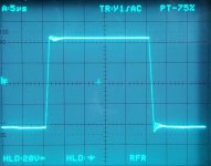
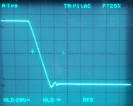
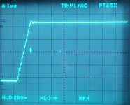
Cherry variant with "short ribbon" cable
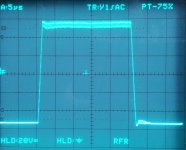
Here some screen shots using short ribbon cable (2 inch).
Note: distortion increased with short ribbon cable (maybe due to less capacitance):
10 inch ribbon cable
Here some screen shots using short ribbon cable (2 inch).
Note: distortion increased with short ribbon cable (maybe due to less capacitance):
10 inch ribbon cable
0.00187% (bw 80 kHz)
0.00225% (no bw limit)
2 inch ribbon cable0.00225% (no bw limit)
0.00250% (bw 80 kHz)
0.00290% (no bw limit)
BR, Toni0.00290% (no bw limit)
Attachments
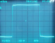
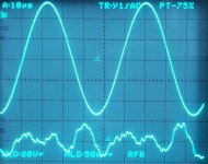
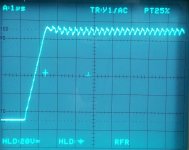
"Cherry" (or OIC) with 2 x 47p and 330p/1R AND suck out cap removed.
Screen shots using long ribbon cable (10 inch).
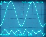
More stability and less oscillation but now we can see an old known instability again ...
Distortion figure for THD21k@200W@8R
Screen shots using long ribbon cable (10 inch).
More stability and less oscillation but now we can see an old known instability again ...
Distortion figure for THD21k@200W@8R
0.00176% (bw 80 kHz)
0.00217% (no bw limit)
0.00217% (no bw limit)
Attachments
As I have informed kgrlee repeatedly, Cherry output inclusive compensation is not stable unless you reduce the second stage's gain drastically at HF (to below unity before the dominant output stage poles take effect) by using shunt compensation at the second stage's output. Told you so kgrlee.
- Home
- Amplifiers
- Solid State
- 2stageEF high performance class AB power amp / 200W8R / 400W4R