Was there any demand for that? Filament power ist the same as in EL34's, btw.
EL152 can dissipate almost twice more power than EL34. If to increase cathode emission, it would work on lower voltages, like EL34, and if to make it's electrodes 1.5 times taller (at least), it would be a killer tube for audio amps.
So I've been breadboarding some preamp circuits and wanted to try some "battery tubes" so, of course, the 2P29L caught my eye. Rather than posting to the 4P1L megathread I thought I'd start a new one.
I'm pretty much a copy and paste builder, not a designer, and my technical knowledge is limited, unlike many of the posters here.
I build low cost, "bang for the buck" stuff. So no expensive plate chokes, vibrator loads, output transformers or trick Rod Coleman filament supplies. Just keepin' it simple using a very basic circuit with parts I had on hand. It's a budget build not a state-of-the-art design.
I used a lower voltage PT at first, which worked OK but I remembered the rule of thumb that says a plate load resistor should be 3 or more times the plate resistance. So that meant using a 15k resistor. To accomplish this I needed more supply voltage so I changed the PT.
The current PS is built around a NOS Halldorson PT I picked up years ago at an estate sale. Because the voltages were getting a bit closer to the 450v rating of the caps than I like, I added a 500 ohm resistor between the rectifier and the first cap. It's definitely not optimal but it's good enough for a breadboard.
The 6BY5 is a dual damper diode which I chose mainly for its soft start characteristic and because I have a bunch. Plus I already had one set up on the breadboard. A different rectifier with more voltage drop might be a better choice and would, perhaps, allow me to ditch the 500 ohm resistor.
Four AAs supply -6.4v of bias to the grid.
Before switching to the 2P29L, I was experimenting with the 1LE3 and using a single AA on the filament. That tube only draws 50mA so the battery lasted a good long while - roughly 24 hours.
Since the filament current is 150% higher for the 2P29L I decided to try a cheap ($3.55) AC-DC regulated switch mode supply. The output is 3.3 vdc and I'm using a 10 ohm resistor to drop it to 2.1v.
From what I've read, I wouldn't be surprised if this filament supply didn't look too good on a scope. I don't have a scope, all I have is my ears.
I started with batteries, then went to battery in one channel and the AC-DC in the other, then both to the AC-DC. I couldn't hear any difference at all. Not saying there isn't any but it wasn't audible to me.
I added a 6800 uF 6.3v cap after the 10 ohm resistor to see if some filtering would be noticeable. I haven't listened to it with the cap much yet. I'll A-B it next week and see if I hear any difference but I figure it can't hurt whether it's audible or not.
I'm not good at describing what I hear but I find it very detailed yet it doesn't exhibit any harshness. And microphonics are not a problem.
I've used the tube in stock form and also with the aluminum shield removed. The nude version looks more familiar - like a small version of a 7868 - but there's essentially no glow at all.
Here's the current schematic. Comments and suggestions welcome, of course.
Hello,
your amplifier reverses the phase, isn't it ?
Is your switching power supply still working well?
Regards
This was a preamp, not an amp. Yes, it does reverse absolute phase. As I understand it, every time the signal goes through a preamp tube section it reverses the phase.Hello, your amplifier reverses the phase, isn't it ? Is your switching power supply still working well?
Regards
If it goes through another section later in the chain it inverts again and you're back to the original polarity. I don't think an output stage affects polarity but I could be wrong. I'm not an expert by any means, so do your own research to get more details.
Whether or not you can hear a difference is debatable and is related to the particular recording.
Not much, if any, attention is paid to absolute polarity during the recording process. As a result, the polarity of different songs are different, even songs on the same album can be different. And, prior to mixdown, the individual tracks are rarely matched in terms of absolute polarity. So a particular song might have some instruments / vocals that are out of polarity with others all within the same song.
Bottom line is that no single setting will work with all songs. If you're really all that concerned about it you need to install a switch that allows you to easily change polarity and then keep a record of which setting you prefer for each song you listen to.
Have fun with that.
This was a breadboard preamp project in which I tried several tubes in the same basic circuit. I ultimately decided to use a different tube (1626) in the actual build and for that design I used a conventional filament transformer. It's an indirectly heated tube so I wasn't too concerned about hum and I figured a DC supply wasn't really necessary.
So I really can't comment about long term reliability of the tiny SMPS I used on this. Note that it is rated at 800mA (2.6W) and the tubes only draw 250mA. I've seen similar (tiny, enclosed in plastic box) supplies on eBay that are rated at 1.5A so you might use those instead. Others use SMPS to heat tubes too, although I'm not sure what particular units they are using.
I never tried the 2P29L with AC heating so I don't know it that's a problem or not but it is a directly heated tube. There was no hum with the DC SMPS, though, and it's a really nice preamp tube. My personal preference was the 1626 but the 2P29L and the 6V7G were really nice too. I think I tried about 10 or 12 different types and those were the 3 that stood out.
Here's a link to a thread about the "Boogie Factor 1626" preamp I built, if you're interested. 1626 Preamp Build | Audiokarma Home Audio Stereo Discussion Forums
I've got another breadboard project at the moment (a SET amp) and I'm trying various DHT preamp tubes (26, 864, 01A, 12A and maybe others). I'm heating those with a Meanwell SMPS which is larger and more sophisticated but still cheap (under $10). Depending on the tube I'm using either a 3.3v supply rated at 10W or a 5v supply rated at 15W. I will be building this using one of the Meanwell supplies.
Hello Flacharlie.
Thanks for taking the time to write so much. I like your philosophy of simple (and low cost), this is where we discover simple and ingenious solutions. For my part, I try to do value analysis and not get into expensive designs. My tubes are Soviet, I buy Chinese components and watch the second-hand market. I collect things that are thrown in the trash and I transform as I go. I thus lead several projects at the same time: Amplifier, Preamp, phono, ... Attached in the photo is my project for a low cost transformer 4P1L preamplifier in progress. No Rod Coleman regulator or Lundhal transformer. However, I really appreciate the accomplishments of Ale, DhtRob and VT52. They are artists! On the photo the fully handmade bases and boxes. the bases are mounted on silentblocs (less than 2 € / 4 pieces) it's a really cheap Ale trick.
I am also interested in your current amplifier project, would you like to post please?
Regards,
Marco.
 [/url][/IMG]
Thanks for taking the time to write so much. I like your philosophy of simple (and low cost), this is where we discover simple and ingenious solutions. For my part, I try to do value analysis and not get into expensive designs. My tubes are Soviet, I buy Chinese components and watch the second-hand market. I collect things that are thrown in the trash and I transform as I go. I thus lead several projects at the same time: Amplifier, Preamp, phono, ... Attached in the photo is my project for a low cost transformer 4P1L preamplifier in progress. No Rod Coleman regulator or Lundhal transformer. However, I really appreciate the accomplishments of Ale, DhtRob and VT52. They are artists! On the photo the fully handmade bases and boxes. the bases are mounted on silentblocs (less than 2 € / 4 pieces) it's a really cheap Ale trick.
I am also interested in your current amplifier project, would you like to post please?
Regards,
Marco.
Last edited:
Hi Marco,Hello Flacharlie.
Thanks for taking the time to write so much. I like your philosophy of simple (and low cost), this is where we discover simple and ingenious solutions. For my part, I try to do value analysis and not get into expensive designs. My tubes are Soviet, I buy Chinese components and watch the second-hand market. I collect things that are thrown in the trash and I transform as I go. I thus lead several projects at the same time: Amplifier, Preamp, phono, ... Attached in the photo is my project for a low cost transformer 4P1L preamplifier in progress. No Rod Coleman regulator or Lundhal transformer. However, I really appreciate the accomplishments of Ale, DhtRob and VT52. They are artists! On the photo the fully handmade bases and boxes. the bases are mounted on silentblocs (less than 2 € / 4 pieces) it's a really cheap Ale trick.
I am also interested in your current amplifier project, would you like to post please?
Nice work. I'm sure that's going to turn out very nicely.
I posted info about my current breadboard SET, including schematics, in this thread since it deals with the same configuration - DHT input tube and IDHT output tube. See post #36:
DHT driver for triode wired SE EL84, 6V6 or EL34
The schematic shows the 26 as input. Only minor changes are needed when other tubes are used.
I have always stayed away from builds using tubes that require "heroic efforts" to eliminate hum and/or microphonics. That's why I liked the 2P29L. Despite being directly heated it had no such issues.
That said, I've read numerous complaints about the 26 and other DHT input tubes, so I was very hesitant to try them. I'm not sure why, but I'm not having any problems with the ST versions I've been using. I suspect the globes are trickier to work with.
The 4P1L seems to be more prone to problems, at least when it's used as a preamp. There is also the 12P17L which is supposedly an indirectly heated version of the 4P1L. I have some but haven't tried them yet.
I built a PP amp using 4P1Ls and they were not a problem when used as output tubes. I'd only heard of them being used SE or PSE in triode so, of course, I used them in PP and in pentode.

Here's a link to that amp: Magnavox 8802 Build . . . With a (Somewhat Different) Twist | Audiokarma Home Audio Stereo Discussion Forums
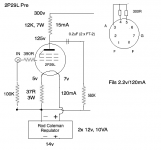
37R*0.12A= 4.44V
The "real" bias voltage -about- 4.44V+1V (Uf/2), about 5.44V.
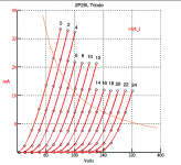
If your goal is 15mA, the estimated anode voltage is about 132..135V.... but it's depends of tube condition.
https://i0.wp.com/www.bartola.co.uk/valves/wp-content/uploads/2016/06/2P29L-triode-model.png
The "real" bias voltage -about- 4.44V+1V (Uf/2), about 5.44V.
If your goal is 15mA, the estimated anode voltage is about 132..135V.... but it's depends of tube condition.
https://i0.wp.com/www.bartola.co.uk/valves/wp-content/uploads/2016/06/2P29L-triode-model.png

I don't think anybody noticed, but way back at the beginning of this thread this schematic was shared, showing a 2P29L based preamp.

That looks like the 2P29L is wired not in triode, but in screen-drive. Isn't it much harder to drive that tube's screen (g2) than its control grid (g1)?
I don't know how relevant it was to compare this circuit to circuits using a true triode or triode-wired pentode using g1 as the control grid.
--
That looks like the 2P29L is wired not in triode, but in screen-drive. Isn't it much harder to drive that tube's screen (g2) than its control grid (g1)?
I don't know how relevant it was to compare this circuit to circuits using a true triode or triode-wired pentode using g1 as the control grid.
--
Andy . . . No, the preamp I built is described in the link in Post #23 above. It uses the 1626 which was brought to my attention by your comments about it over the years. Thanks again!Do you have this up and running now? Any listening impressions?
As I said above, "My personal preference was the 1626 but the 2P29L and the 6V7G were really nice too. I think I tried about 10 or 12 different types and those were the 3 that stood out. "
I'm not nearly as good at describing tonal qualities as you are but I would say that the 2P29L sounded more pristine to my ears, as did the 6V7G. Given that you mostly listen to different types of music than I do, you might want to give the 2P29L or 6V7G a listen.
On a side note . . . in Post #25 above, I included a link to another thread in which we were both participants, dealing with the "inverted SET" amplifier topology. At the time I had just started to breadboard one.
I finally got around to building it. It's another one of my low cost, bang for the buck, builds using junkbox parts and repurposed materials. So, pretty much the antithesis of what those who post here are into.
If you're interested, here's a thread about it that I posted over on AK:
https://www.audiokarma.org/forums/index.php?threads/the-nuance-my-inverted-set-diy-project.990205/
I now have a 2P29L preamp up and running and listening to it now. It has a buzz right now which could be an earthing issue or possibly the DC supply to the filaments. But I can already hear that it sounds very good indeed. I've been using a 6SN7 as driver tube for my 2a3 amp, and this works fine with input straight from my DAC. So I put this preamp in front of the 6SN7 driver. The sound is maybe slightly improved - the 2P29L is clearly sounding better than the 6SN7. I'm surprised that adding a stage could improve the sound.
So here is the schematic. I went for simplicity, so this time no filament bias. I could probably improve the DC filament supply. Larger capacitors and a dropper resistor between first and second cap. I could add a choke even though that might be overkill.
Comments welcome.


So here is the schematic. I went for simplicity, so this time no filament bias. I could probably improve the DC filament supply. Larger capacitors and a dropper resistor between first and second cap. I could add a choke even though that might be overkill.
Comments welcome.

Hi Andy - the 2P29L filament may only be 120mA, but it is still very sensitive to the supply quality.
Running a 330R cathode resistor unbypassed is marginal for a preamp, because the primary to secondary leakage current of the PT will run through it. For a typical EI 50VA the leakage current is ca. 10uA at 240V.
You get this 50Hz (or 60Hz) leakage current in the cathode resistor regardless of any filter or regulator, as it is common mode.
Also, the unbypassed cathode resistor will increase the intrinsic anode resistance (ra or rp), which is not advisable for driving the anode choke.
Give it a try with the V9 regulator you have, and put the filament bias back in! The 1085 makes a mediocre current source, faced with the upper audio frequency range.
Before that, bypass the Rk with a decent 470uF cap (cheap Panasonic M is plenty good enough to demonstrate) to show what you're missing with the anode drive.
Thanks Rod - I used to use filament bias and your regs with the 2P29L years ago. I just tried cutting corners this time.
You say "Running a 330R cathode resistor unbypassed is marginal for a preamp, because the primary to secondary leakage current of the PT will run through it. For a typical EI 50VA the leakage current is ca. 10uA at 240V. You get this 50Hz (or 60Hz) leakage current in the cathode resistor regardless of any filter or regulator, as it is common mode."
So is this problematic with the size of the resistor, 330R? How about if it is bypassed, or if you use filament bias? What happens then?
Yes, as the value of the resistor increases, the risk of problems increases.
With a standard industrial EI PT, rated 50VA, 75pF leakage current means about 43Mohm of reactance at 50Hz, and so the current (common mode) is ca. 5.7uA at 240V. So an unbypassed resistor drops 1.8mV rms in this case. This is high for a line stage.
This current only has one place to run to ground - through the cathode resistor. And as it is common mode, no reasonable filter, nor regulator can block it.
If you have a filament bias resistor of value 50R (say), the voltage is nearer 0.3mV.
Measurements and calculated values agree here.
At 120V mains supply, the leakage current is half to this value.
You can also use a PT with lower leakage, perhaps an R-core, to get lower drop.
Or you can bypass Rk with a larger-than usual capacitor, to give low overall impedance at 50Hz.
Andy - you might also consider battery grid bias as I did in the schematic in Post #31 above. The cathode resistor in that scheme is simply used to drop the filament voltage from the particular source I used, so it may not be needed if you don't require a voltage drop.
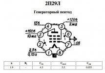
I'll note again that, while the tube was not drawn right, the pin numbers are correct.
It can also be implemented with the battery in series with the grid. This allows you to eliminate the DC blocking cap on the input. Of course, if your source has a cap on its output, that isn't needed anyway. The downside of the series arrangement is that you have to use a battery for each channel instead of a single battery for both.
The series arrangement is what I use to bias the 26s in my Nuance iSET. See the link in Post #34 for a schematic.
Battery life in such an arrangement is essentially equal to the shelf life of the battery, perhaps as long as 10 years for a lithium. If you've never tried battery grid bias you should at least give it a listen.
Thanks Charlie. I did try battery bias in the past. I didn't carry on with it so must have found something I preferred - probably filament bias. I've been building a filament bias version which is near to finishing and trying out. It's not difficult to set up - 2P29L is very easy to work with. I'll use a 15K anode resistor and around 4v on the cathode for about 12.5mA. Then go from there.
- Home
- Amplifiers
- Tubes / Valves
- 2P29L Preamp