I totally agree sonidos. I've learned a lot from Ivey and i love riaa circuits, i built dozens of riaa phono stage with tubes, bjts, fets, etc.
Thanks Ivey, wherever you are now, great man, and technician!!!
Maybe Ivey Riaa is not the best but i think that certain "finesses" in his topology had to be developed.
In memory of Ivey i studied his circuit in my multisim, started to test in real life and i would like to share my implementations and optimized components values. For an "old" riaa, calculated by hand, it's a great result!
If you want i will show my "tribute" to Ivey with my schematic and graphs from simulator, than a simple pcb with or without his series regulated supply, so similar to that i used for years with excellent low-noise satisfaction in musicality.
Are you curious?
Sonically yours,
Gianni
Count me in.
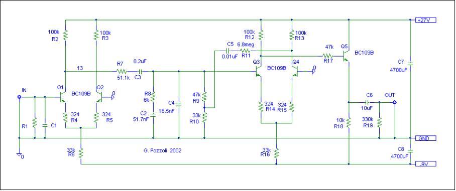
Cascaded diff amps with passiive Riaa and a bootstrap.
I build this one, in a spider web & point to point & match BC109 ... & accu PSU.
It's magic (even with a card MM Grado-gold) ... It's music ... I love it.
I know well that phono pre. I don't like it for many reasons:I build this one, in a spider web & point to point & match BC109 ... & accu PSU.
It's magic (even with a card MM Grado-gold) ... It's music ... I love it.
No real need for a differential stage without global feedback, according to me.
Hi value resistors both for the bjts and passive riaa, so bye bye to the bc109 noise figure.
The bootstrap is not worse than moderate global feedback that gives more control to the full circuit and less device-dependent. I prefer local feedback but we are talking of a cheap and realiable phono stage here.
Regards,
Gianni
Here's the old Ace circuit:
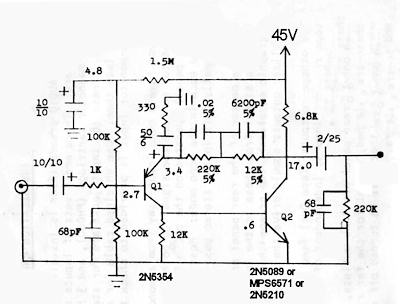
I changed my output cap to 10uF/50V, the 6.8K to 12K and the 12K to 10K, probably for the zero distortion mod. Their addendum listed a couple of other changes as well.
CH
Conrad, I used your circuit, and replace the recommended transistors with the following units PN3638A and PN3565. Then I reduced the voltage to 25 volts.
And it sounded really good with no ringing.
hi Ivey.
the design of the post 23 and 24 has been tried and does it work?
I'd like to build your pre but I have a question regarding the in and out electrolytic capacitor: can replace with a MKP 0,1uf/1uf?
thanks in advance for your help and sorry for my terrible english.
the design of the post 23 and 24 has been tried and does it work?
I'd like to build your pre but I have a question regarding the in and out electrolytic capacitor: can replace with a MKP 0,1uf/1uf?
thanks in advance for your help and sorry for my terrible english.
hi Ivey.
the design of the post 23 and 24 has been tried and does it work?
There are some pretty substantial errors in most of the schematics he posted. For example, one of the 2N2222A phono preamps has a 1uF cap from input to ground, or there's the 12AU7 cathode follower that biases the grid positive WRT by design.
Your best bet is to try Gianni's version of the circuit.
I just came across this thread today and read every post. Sad to see Ivey has passed as the knowledge he gave on these transistors really impressed me. I have built a version of this preamp before using numerous transistors to much success. I cannot remember where I got the basis for this but it was an old book on amplification. This thread amazed me how it went from a basic design from the 50s to gianxdiy's schema that I just built in multisim to check out. I just learned a lot and I have been building amps for 19 years. Thanks diyAudio and all the participants in this thread! Good Stuff!
work in progress: 2n2222A in TO-18 metal case pre phono "a la gianxdiy".
An externally hosted image should be here but it was not working when we last tested it.
An externally hosted image should be here but it was not working when we last tested it.
An externally hosted image should be here but it was not working when we last tested it.
An externally hosted image should be here but it was not working when we last tested it.
I just came across this thread today and read every post. Sad to see Ivey has passed as the knowledge he gave on these transistors really impressed me. I have built a version of this preamp before using numerous transistors to much success. I cannot remember where I got the basis for this but it was an old book on amplification. This thread amazed me how it went from a basic design from the 50s to gianxdiy's schema that I just built in multisim to check out. I just learned a lot and I have been building amps for 19 years. Thanks diyAudio and all the participants in this thread! Good Stuff!
Thanks twbranch!
That may have been some shunt capacitance to simulate cable capacitance. You can likely just leave that off.
Exactly!
")
I am not in to phono things ...The thread was in front of me and i spend some hour to read it all .
Sorry to hear about ivey past away
What was important about him was his passion Passion about what he did and good knowledge of the parts he was working with
In reality very few know that much in such a depth of the parts are working with proper use of parts have been always an issue in commercial audio Often part selection was done by the marketing rather than the designer
Often machines using the exact same family of parts sounded totally different.Proper use of parts made extreme difference.
Closing Argument :
In the repair business and when you repair 1000 audio devices per year you are probably listen to opinions.
Also opinions of course is like a**holes everybody's got one ( quoted from Dirty Harry )
Statistics though from so many a**holes edit : sorry opinions is that SIMPLE MACHINES TENT TO PLAY BETTER !!
My 2 cents
My respect to the man and his admirable passion!
Sorry to hear about ivey past away
What was important about him was his passion Passion about what he did and good knowledge of the parts he was working with
In reality very few know that much in such a depth of the parts are working with proper use of parts have been always an issue in commercial audio Often part selection was done by the marketing rather than the designer
Often machines using the exact same family of parts sounded totally different.Proper use of parts made extreme difference.
Closing Argument :
In the repair business and when you repair 1000 audio devices per year you are probably listen to opinions.
Also opinions of course is like a**holes everybody's got one ( quoted from Dirty Harry )
Statistics though from so many a**holes edit : sorry opinions
is that SIMPLE MACHINES TENT TO PLAY BETTER !! My 2 cents
My respect to the man and his admirable passion!
Last edited:
Ok, let's start!
Major improvements are:
Less distortion: from 0,3% to 0,03% @5mVrms - 1KHz
More headroom, especially in high band: before it was 2dB @20KHz, now 10dB!
More accurate RIAA curve: now is within 0,2db with E12 series!
Less noise: now it's under 80dB @1KHz and under 65dB @20KHz.
Added the possibility to tune-up the MM with an additional loading cap and/or resistor (asked during the thread).
I prefer a light subsonic filter under 40Hz, it's easy for everybody to modify a capacitor if you want to go flat @20Hz.
I use 2n2222A in TO-18 metal case and i love this simple and old circuit!!!
I would like any feedback, i will answer to tell my point of view and my choices.
Regards,
Gianni
NOTE:
R28 is 47k for simulation. Use 470k in real life!
Last edited:
- Home
- Source & Line
- Analogue Source
- 2N2222A phono preamp