This one works well
or you can run it with just one 2A3 which I like better
View attachment 2A3_PSE_6SN7_6SN7_2K-2.pdf
The transformers can still be obtained from UK winders
or you can run it with just one 2A3 which I like better
View attachment 2A3_PSE_6SN7_6SN7_2K-2.pdf
The transformers can still be obtained from UK winders
Chris,nicely documented and assembled project
I deeply appreciate your warm words of support.
Regards, Konstantin.
Here's one that meets the criteria. SE, two gain stages, no FB, low part count, and nothing exotic. I can vouch for it. I've built an 801 amp, based on the same idea. http://www.diyaudio.com/forums/tubes-valves/125488-loftin-white-801-amp.html#post1551490 Power supply is simple LCLC or CLC supply. All capacitors can be film caps, as no large caps are required. It sounds very nice and is as quiet as a grave (I often use it as a headphone amp).
I didn't use the bootstrapped follower, as I didn't need a higher gain input tube. But I will try it at some point. You don't have to use the same tube for the input and follower, but it will work well that way. Darius (former member oldeurope, who developed the amp, has a 300B version). With a 2A3 you can probably do fine with AC heating on the filament, if you don't want the complexity of a DC heater supply.
Sheldon
BTW: Even if you don't build it, it's worth studying. Those guys (L-W) were clever and subtle.
One last thought: Once set up, the operating points are self settling. It requires no adjustment, and stays stable for the life of the tubes.
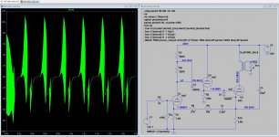
Sheldon, somehow the driver stage oscillates crazy. I tried from 1k to 20K for the R6 feedback resistor without luck, am I missing something here?

Attachments
Last edited:
Sheldon, somehow the driver stage oscillates crazy. I tried from 1k to 20K for the R6 feedback resistor without luck, am I missing something here?
I see two major problems with that schemo, and that's aside from trying to use a 6SL7 as a grid driver for a 2A3. (attached) These low gain, DHTs need stiffer grid drivers.
The grid stopper is in the wrong place. That 1K stopper needs to be connected directly to the grid pin with as short a length as possible. It should be the only connection to the grid, and connecting the DC return resistor to the grid pin defeats the purpose. Stoppers are supposed to load down and de-Q parasitic resonant circuits.
Another problem is that the cathode follower section doesn't have a grid stopper. Despite that cathode followers have less than unity gain doesn't mean they can't oscillate, Colpitts style, due to device and stray capacitance, and stray inductance. It's especially likely when connecting to a Hi-Z source and a 6SL7 with a 200K plate resistor bootstrapped to near CCS conditions is indeed very Hi-Z. Followers sometimes need grid stoppers as well as bypassing right at the plate (0.1uF ceramics are good for RF bypassing there, and install with the least lead length).
The other problem is that the R5 + R6 + C1 network isn't doing anything. The cathode of the 2A3 is at AC ground since that 3K8 cathode resistor is bypassed with that 25uF capacitor. Diddling around with its values will accomplish nothing.
Attachments
I'll go with Miles on everything except the feedback to the input cathode. Yes the output cathode is referenced to common, but not perfectly. At least in my original build (still using), with a pot in that chain, I can dial the output hum to a clear minimum. I don't see that the effect would be different with the follower in place. But, try with and without the feedback and see.
Sheldon
Sheldon
- Status
- This old topic is closed. If you want to reopen this topic, contact a moderator using the "Report Post" button.