burnedfingers said:The AZ1 is a nice looking tube. I have seen several in the last 10 years or so but haven't ever come across a base for one. Can't say I have ever heard a sonic difference between different rectifier tubes with the rest of the supply staying the same. I would suggest staying away from the 83 tube. Mercury is not our friend.
To the contrary I find any rectifier substitution very audible across the whole tonal range. Keeping the voltages the same. I agree that mercury tubes are hazardous, and if a 274B ($90 for TJ) is expensive, my next recommendation would be a 5R4GY RCA.
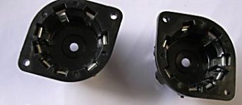
*There are 8 pin P-Sockets available for AZ1 if someone wants to utilize this sweet, open tone rectifier in a new DIY project. They cost about 3.5 EUR per piece.
Attachments
Hi Arnold,
Magnequest made suitable 15K:600 ohm output transformers for this design at one point. I suspect the Hashimoto 20K:600 would also be an excellent choice, slightly lower gain than the 15K:600 Magnequest.
Tango/Iso and TamRadio (Tamura) also make suitable transformers - it depends a lot on your budget.. The table in the article provides guidelines for selecting a suitable transformer, the key is to choose a vendor known for their high quality as this is literally the heart of the pre-amplifier. (I am not affiliated with any of these folks.) Electra-Print could also make you a pair of these, but I wonder about the economics of then shipping them to your end of the world - still that might be a good choice. (I am a happy customer, no other affiliation.)
To test the regulator you need to load it, although it should regulate ok without a load for preliminary testing. Still I would recommend hanging a 47K/1W resistor across the output - it will be dissipating a little less than a 1/2W so it will get quite warm.. It should be safe to connect it to the pre-amp circuitry even without taking these precautions if you use a variac and/or ballast lamp.

next recommendation would be a 5R4GY RCA.
Why on earth would you waste a 5R4GY when your current draw isn't anywhere near what the 5R4 is capable of. A 5AR4 or 5Y3 would surely supply the needs of this line stage.
Sorry, I don't agree with different rectifiers having a special sound. I can hear a difference between SS and tube rectifiers. I cannot however hear a difference between the 5R4,5y3,5AR4,5U4,5V4 and others I cave tried in the same circuit.
If your going for looks the AZ1 is a nice. There is another site where the builder used a AZ1 for its cool mesh plate.
There are 8 pin P-Sockets available for AZ1 if someone wants to utilize this sweet, open tone rectifier in a new DIY project. They cost about 3.5 EUR per piece.
I would be open to trying an AZ1 if you would like to find me one at a reasonable price and point me toward a supplier for the P-socket.
In a 26 preamp, everything will be audible. I am not recommending rectifiers here on technical requirement but on subjective performance experience. When someone goes for a DHT preamp, he is not counting mA or $$$, he just relentlessly pursues tonal beauty and inner musical light. A 26 preamp is like building a violin not an apparatus. Trust me, rectifiers are dead easy audible even in a 12AU7 preamp. They are easily distinguishable not only by type but per brand and vintage also. I have done many experiments and I am positive about that. AZ1 is really great, clear as a bell. P-Sockets here, and on E-Bay.
Kevin, if you are still following this thread I hope that you (or someone else) could answer a few questions regarding the implementation of your 26/01a preamp:
1) There is a 20K resistor going from the bottom of the bias pot to ground. Should this resistor be removed when using battery bias?
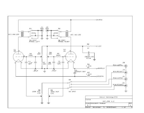
2) I am a little afraid of too lowish gain. Any suggestions regarding specs for a suitable input transformer.
3) When running the filaments on batteries, I suppose that switching to "charge mode" with B+ on will severely reduce the life of the tubes? A relay arrangement that switches B+ off when going into "charge" mode would be required, right?
1) There is a 20K resistor going from the bottom of the bias pot to ground. Should this resistor be removed when using battery bias?
2) I am a little afraid of too lowish gain. Any suggestions regarding specs for a suitable input transformer.
3) When running the filaments on batteries, I suppose that switching to "charge mode" with B+ on will severely reduce the life of the tubes? A relay arrangement that switches B+ off when going into "charge" mode would be required, right?
Hi,
For battery bias just delete the pots and resistors and connect directly to the grid resistors.
You don't need to disconnect the B+ when charging the filament batteries, this would not have been done in the old radios these were originally used. If the B+ is not battery derived I would shut the B+ supply off to save power and improve reliability.
Unless you have very big filament batteries run time will be pretty limited between charges. I'm not a big fan of battery filament supplies.
Using ots transformers the gain options are limited to those listed in the table in my article. You can play games with the secondary impedance by increasing it to 1.2K or even higher with a custom opt.
I don't know how much gain you need but with 15K:600 the overall gain is ~ +4dB..
kevinkr said:
I would be happy to advise simplification where possible. The earlier version uses a simpler B+ supply using a single 6EM7 - rectification can be tube or SS. I can furnish a schematic on fairly short order i f you want one.
Kevin,
yes, please do provide us a schematic.
TIA,
-- josé k.
Hello,
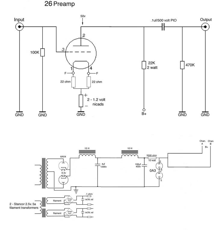
Can anyone suggest improvement to this 26 pre. I use 2- 6w4 damper diodes for rect & slightly differant PS values. PS in seperate wood chassis. I do not seem to have the microphonic issue that most have. I also at this time just use a lab supply for filaments. I have all of Kevin's 26 info prmted & organized, many pages to study there, but that will be one I slowly get parts for. of course the trannies will be the $. Mine is simple, but yet still sounds excellent. I am sure there are things I could change in this schematic for the better..PT is a 250-0-250v
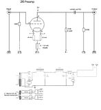
Can anyone suggest improvement to this 26 pre. I use 2- 6w4 damper diodes for rect & slightly differant PS values. PS in seperate wood chassis. I do not seem to have the microphonic issue that most have. I also at this time just use a lab supply for filaments. I have all of Kevin's 26 info prmted & organized, many pages to study there, but that will be one I slowly get parts for. of course the trannies will be the $. Mine is simple, but yet still sounds excellent. I am sure there are things I could change in this schematic for the better..PT is a 250-0-250v
bequerel said:Thank you for your reply, Kevin!
If I start building I will probably use the 01a tube with CCS above the output transformers.
I presume you mean parafeed configuration? If you use a CCS you want to set the quiescent current to about 6mA for the 26, and about 3mA for the 01A.
Hi Kevin,
You familiar with the Lundahl LL1660? (not the S) - http://www.lundahl.se/pdfs/datash/1660.pdf
I think it can be used as line output, but I'm not sure if it would match the 26 or 01. What spec should I be looking at for an alternative line output transformer? Without loosing so much gain...
If I parafeed as mentioned above, what would be the specs?
Hi Arnold,
Pretty much in all cases I recommend 15K:600 ohm and enough primary inductance to get down to 20Hz within a dB or so of flat. Something in excess of 150H is probably required at the requisite quiescent current - that is why these transformers are so expensive.
Same goes for parafeed, but as there is no dc current flowing in the windings they can be made smaller and may perform slightly better than a comparably priced conventional plate to line transformer.
Note if you need more gain it might be a better idea to dispense with the 600 ohm output impedance and specify something like 1200 which will give you 3dB additional gain. Note that primary inductance should remain the same. (This of course is only relevant if someone is building custom transformers for you. Hint: Consider Electra-Print )
I took a moment to look that transformer over, and it really doesn't seem suitable. You really need something with a 5:1 ratio and 150 - 200H primary inductance in SE configuration. (This is the 15K:600 previously mentioned.) Hashimoto makes a 20K:600 that would be suitable but would result in lower gain. (see article)
Hi,
The 499K resistor is not a grid stopper and appears in parallel with the pot wiper. You can use something as small as 100K depending on the value of your pot. Lower values do load down the pot and will modify the taper, generally you want something like 10X the highest resistance at the wiper to minimize this effect. For a 100K pot the max R at center is 25K so to minimize this issue you would select a 249K resistor. Etc...
The 499K resistor is not a grid stopper and appears in parallel with the pot wiper. You can use something as small as 100K depending on the value of your pot. Lower values do load down the pot and will modify the taper, generally you want something like 10X the highest resistance at the wiper to minimize this effect. For a 100K pot the max R at center is 25K so to minimize this issue you would select a 249K resistor. Etc...
- Status
- This old topic is closed. If you want to reopen this topic, contact a moderator using the "Report Post" button.
- Home
- Amplifiers
- Tubes / Valves
- 26 preamp