Hi John,
I always use common chassis for HV and LV PSUs ... but don't use there (in the PSU chassis) common ground.
In my usually practice all PSUs are "floating" in the PSU box.
I use separated power transformers, separated raw PSUs, separated umbilical parts.
Each PSU negative and positive output passes trough individually in umbilical (tightly twisted, sometimes -if needed- screened).
The PSU box power line input protecting ground tied to metal box near to the power connector.
From this ground point one grounding wire pass trough in umbilical to preamp box.
In the preamp box each part insulated from box metal parts.
Only the grounding wire connected to preamp box metal part.
I hope this helps a little.
Hi euro21,
Thanks for your response!
My filament supplies are floating, of course. They won't work otherwise.
However, I do have the HV 0v tied to the chassis ground (earth/safety) at the PSU. I didn't try lifting that ground. Might try that.
The hum I am experiencing isn't any where near as loud as a classic earthing ground-loop mistake. On my EL34 PP amps, for example, if the chassis ground (earth/safety) is lifted, the hum is LOUD.
Best regards,
John
Hi John, I am no expert, but hoping that sharing my experience here is helpful to you and others. I had been trying to sleuth around my chassis to diagnose the hum problem. Mine worked at first as well, without hum, but then as I tried more things and changed the layout, it started becoming audible, even if only at the speakers.
What I found is similar to you, which is that it has everything to do with the cathode. Unless a gross mistake is made in the earthing and grounding, it all comes down to what is happening at the cathode because whatever happens here gets magnified by the gain of the tube. You are finding the same thing, which is that powering from batteries works very well.
In my case, I have arrived at SiC diode-based cathode bias (not filament bias) as the best sounding. I am using Ale's SiC diode board that can carry 6 diodes. In my layout, on some 01a tubes a high bias resulted in hum and I narrowed it down to the last triplet of diodes (which I have shoved into one spot to get up to -10V bias). If I omit that last group of three diodes, the hum goes way down. So, that last group is probably catching noise because the legs form somewhat of a loop. Of course, a 100uF cap bypassing the diode string makes things dead quiet, but this is not needed at lower bias values on the 01a. Also, some tubes are just a lot quieter than others. I would suggest continuing paying attention to the cathode and the layout there.
BTW, I really butchered this chassis in an attempt to learn. I flipped it around, mounted the transformer on the top, covered the trafo with a cover, did several other layouts with the chokes, rectifiers, etc. One layout where the tube rectifier was close to the gyrator boards produced audible hum--I presume this is because the tube heater AC gets picked up elsewhere. But all other layouts had very little impact on the noise. My conclusion from this is that you can put the PS and signal wiring in one chassis as long it is nicely subdivided and you pay attention to the 0V connections. Partly, it was to convince myself that I could achieve low noise in this layout.
Also bought a couple of books from Merlin Blenclow and Morgan Jones that have helped a lot on understanding the sources and mechanisms of noise and hum coupling.
Hope this helps.
Last edited:
I haven't had many hum problems with DHTs using Rod Coleman filament supplies.
In my case, though, I use choke input filament supplies and filament bias. I'm a fan of chokes in general, and I think it's worthwhile using them in a filament supply with a DHT. In filament bias, the supply needs to be uber clean, of course. I think overkill is not madness here.
In my case, though, I use choke input filament supplies and filament bias. I'm a fan of chokes in general, and I think it's worthwhile using them in a filament supply with a DHT. In filament bias, the supply needs to be uber clean, of course. I think overkill is not madness here.
Hey!
Thanks Ra7 and Andy for chiming in, here!
I think my earlier post (#5098) was misconstrued. I am actually quite happy with the battery solution for the 2p29L filaments. The voltage and current are low enough to make this feasible. Sound is great, noise is very low.
It would work even better if I converted to cathode bias. With 3 18650 cells in parallel, I could probably get ~60 hours on a single charge.
Hmm... Though, I may try battery powering the Coleman Regs just to see if that changes anything. Might be good to figure out what is causing them to hum a little in this situation.
Best regards,
John
Rectifier Tubes
Hi All,
What are some full-wave glowing (literally) alternatives to the AZ1 rectifier tube? Need options that have a nice glow.
The AZ1 is nice but it doesn't glow and the 26 tubes don't glow either. The 01a tube has a nice glow near the bottom where there is less getter.
Thanks!
Hi All,
What are some full-wave glowing (literally) alternatives to the AZ1 rectifier tube? Need options that have a nice glow.
The AZ1 is nice but it doesn't glow and the 26 tubes don't glow either. The 01a tube has a nice glow near the bottom where there is less getter.
Thanks!
") , at least for one version of the preamp. Planning to build some more with different tubes and topologies. But want the rectifier to be something easy on the eye.
, at least for one version of the preamp. Planning to build some more with different tubes and topologies. But want the rectifier to be something easy on the eye.I hadn't looked at this thread in quite a while but since I've been breadboarding an amp with a 26 I thought I'd read through some of the most recent posts.Hi Rod,
Thanks, as always, for your help!
First of all, let me state the obvious: This is not any fault of your Reg boards. They are great. It is something going on at my house. Like I said, my type 26s will howl and moan like an amorous banshee if they are not fully shielded. I ended up with a heavy-gauge steel box to enclose the whole circuit, and a shielded PS umbilical.
It is also not uncommon to pick up some RF noise when I hook up my solid state amps.
I forgot to mention in my last post that I also tried the filament regulators back in their original position, and still got the hum.
I think that perhaps I just didn't notice it before I reworked the layout.
All the signal wiring is coax. I even tried a shielded anode wire. None of it helped.
I'm actually not that picky about a little hum. But once I did notice it, I thought it might be good to try and get rid of it.
My HV and LV PSUs are on a single chassis. Maybe I should try to split them up?
The induced noise would be from HV to LV (is this the right way to put it?), I think, because when I use the battery powered filaments with the LV supply powered (but idle) there is no hum.
Thanks, again, for your input.
Best regards,
John
John - Have you tried using a more conventional chassis arrangement with more space? Perhaps it's not a contributing factor but it seems like you have a lot of parts piled up in such a small area that it may be creating problems. Just a thought.
When I first looked at this thread years ago it actually discouraged me from trying 26s. Too many reported issues with hum and microphonics.
To my surprise, it's not giving me any problems at all in my current breadboarded SET.
A while back, I also breadboarded about a dozen preamp tubes including the 2P29L. I tried it because it has a reputation for not being microphonic. I liked it a lot - it was in my "top 3" - although I ended up building with a different tube.
Here's a thread about my breadboarded 2P29L, if you're interested.
2P29L Preamp
I had no issues with it either. No shielded wire or anything. The PS and signal sections were in close proximity on my total mess of a breadboard with many connections using clip leads. I heated them with some tiny AC-DC SMPS that I found on eBay. I also tried a battery and I couldn't hear any difference at all. I used battery grid bias.
I'm following the same path with my current SET project using the 26. Still using battery grid bias but with a higher quality Meanwell SMPS for the filaments. I also added a VR tube and inexpensive Hammond 156C chokes in the plate supply.
I've also used the 01A and 12A and no problems with them either.
Last edited:
Simply use a glow tube if you want a tube to glow. Rectifiers don't glow.
A glow tube or voltage regulator is a useful addition to the PSU anyway.
Depending on the glow tube you get pink, yellow etc. There you go.
Thanks Andy! I'm going to go with a mercury vapor rectifier for the next build. See what that does.
Thanks Andy! I'm going to go with a mercury vapor rectifier for the next build. See what that does.
Mercury is highly poisonous and many including me wouldn't even dream of using a mercury rectifier. Be warned!!!
Thanks Andy! I looked it up and there is a thread here on diyaudio about the hazards--simply not worth the trouble. No MV rectifiers then.
Gideon, 3B28 may be fun to try one day. For now, I need a full wave rectifier. Probably will have to give up on the glow.
Been using PSUD2 to sim some rectifiers. There are many options. Is there a suitable one where there is not so much loss of voltage? The type 83 was attractive because, apart from the glow, it did not lose a lot of voltage. Would be nice if it compliments the look of the vintage globe tubes (26/01a/801a).
Meanwhile, here is a pair of 10y tubes in operation using the same basic circuit as the 26/01a. They produce some truly astonishing sounds. The very air seems to be charged with the atmosphere of the recording.
Attachments
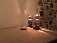
Meanwhile, here is a pair of 10y tubes in operation using the same basic circuit as the 26/01a. They produce some truly astonishing sounds. The very air seems to be charged with the atmosphere of the recording.
You won't get anything better than 10Ys with an AZ1/AZ11 mesh rectifier, or if there is anything better I haven't found it in 12 years of building with DHTs. Arguably 46, 47 or 49 but the 10Y can be used in filament bias so no cathode bypass cap. A nice big choke input filament supply and Rod's regs and you're good to go.
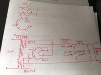
Another diyer had asked for my PS diagram over PM. Attached. I'm hardly an expert, so please feel free to suggest improvements. It is based on the supply that Amandarae showed in earlier posts (around page 500).
Thanks, ra7!!
Well noted!
Guys,
has any one tried to replace AZ1 for 4 diodes or a rectifier bridge? Wondering to give a try but not sure if i will mess it up...
Just for your info, I will use Salas SSVH2 to regulate B+.
Appreciate your hints.
Cheers,
Mutuano
Last edited:
AZ1 is roughly equivalent to the AZ11 and RGN1064, slightly different C1 specification but about the same current capability.
If you want to replace a bridge with 4x AZ1 you also need 4 different 4V windings.
But once you use the sallas shunt you go from high impedance to a low impedance supply. In which case the rectifier tubes are nothing but glorified lightbulbs that rectify.
Cheers,
V4LVE
If you want to replace a bridge with 4x AZ1 you also need 4 different 4V windings.
But once you use the sallas shunt you go from high impedance to a low impedance supply. In which case the rectifier tubes are nothing but glorified lightbulbs that rectify.
Cheers,
V4LVE
AZ1 is roughly equivalent to the AZ11 and RGN1064, slightly different C1 specification but about the same current capability. If you want to replace a bridge with 4x AZ1 you also need 4 different 4V windings. But once you use the Salas shunt you go from high impedance to a low impedance supply. In which case the rectifier tubes are nothing but glorified lightbulbs that rectify. Cheers, V4LVE
I use 2 x AZ11 in parallel. So just one 4v supply. And a hybrid or Graetz bridge with UF4007s for the negative side.
You're right - I should build a Salas reg. Everyone raves about them.
- Home
- Amplifiers
- Tubes / Valves
- #26 pre amp