Each cascode plate load construction (CCS and "gyrator" too) requiring at least 25-30V more B+ voltage as maximum plate swing peek.
In practice I never use its below 50V headroom... if it possible.
I use kV capable FETs as "upper" device, so B+ voltage practically not limited (for example up to +600V).
My CCS loaded 841 VAS stage working with +620V (but only at 9mA current).
In practice I never use its below 50V headroom... if it possible.
I use kV capable FETs as "upper" device, so B+ voltage practically not limited (for example up to +600V).
My CCS loaded 841 VAS stage working with +620V (but only at 9mA current).
Having Fun!
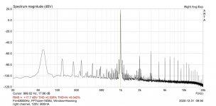
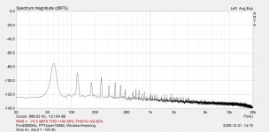
This morning I hooked up the preamp to the soundcard and ran measurements at different operating points. See attached pics. It shows the THD, THD+N, and distortion spectra for a 1 kHz fundamental. Measurements performed using the RME ADI-2 Pro, which was calibrated using ARTA, though I'm pretty sure the calibration process has some bugs.
I basically had two pots to play with: the anode voltage and the filament current. I'm using the filament bias scheme with a 10 ohm resistor.
Here's what I found:
- Distortion is not sensitive to filament current. I tried all the way from 1.0 amp to 850 mA at different plate voltages and it doesn't make a big difference. So, I settled on 900 mA as a middle point.
- Total distortion and the products are very sensitive to plate voltage, as expected.
- Referring to the images below, the first one shows anode voltage at 120 V. THD is the lowest among all settings, but the 3rd is higher than 2nd and there are higher order products at quite a high level.
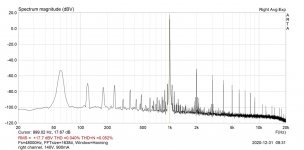
- Going up to 140 V increases THD, but higher order products are reduced and the products are ordered in a monotonically decreasing fashion. I've read that this is what sounds the most linear to the ear.
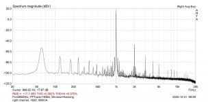
- Going up to 160 V, THD increases further but most of that is driven by the second harmonic and higher order products are much lower.
Anyway, this whole experience was fascinating to me. Subjectively, the 160 V point sounds way better than the 140 V point. I haven't yet explored the 120 V point.
Is there a way to separate the grid-to-cathode voltage setting from the filament current? Currently, the two are tied together. I know there are different schemes, cathode and fixed bias, but I'm wondering if there is an "easy" way to do it in my build.
This morning I hooked up the preamp to the soundcard and ran measurements at different operating points. See attached pics. It shows the THD, THD+N, and distortion spectra for a 1 kHz fundamental. Measurements performed using the RME ADI-2 Pro, which was calibrated using ARTA, though I'm pretty sure the calibration process has some bugs.
I basically had two pots to play with: the anode voltage and the filament current. I'm using the filament bias scheme with a 10 ohm resistor.
Here's what I found:
- Distortion is not sensitive to filament current. I tried all the way from 1.0 amp to 850 mA at different plate voltages and it doesn't make a big difference. So, I settled on 900 mA as a middle point.
- Total distortion and the products are very sensitive to plate voltage, as expected.
- Referring to the images below, the first one shows anode voltage at 120 V. THD is the lowest among all settings, but the 3rd is higher than 2nd and there are higher order products at quite a high level.
- Going up to 140 V increases THD, but higher order products are reduced and the products are ordered in a monotonically decreasing fashion. I've read that this is what sounds the most linear to the ear.
- Going up to 160 V, THD increases further but most of that is driven by the second harmonic and higher order products are much lower.
Anyway, this whole experience was fascinating to me. Subjectively, the 160 V point sounds way better than the 140 V point. I haven't yet explored the 120 V point.
Is there a way to separate the grid-to-cathode voltage setting from the filament current? Currently, the two are tied together. I know there are different schemes, cathode and fixed bias, but I'm wondering if there is an "easy" way to do it in my build.
Attachments
Last edited:
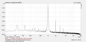
Your measurement shows that you have a little hum problem (probably in the preamp).
The 60Hz component is relatively high, and sidebands is visible around the 1kHz base and harmonics.
Each #26 (01a are less) preamp is hum sensitive.
1.) The tube itself very sensitive to radiated hum, varies from piece to piece (even 10-15 dB difference occurs).
2.) The filament biased construction is sensitive, the non inductive bias resistor capable behaves like antenna.
3.) If you have unsatisfactory separation from anode supply (R or choke load), the 100/120Hz hum is appears.
In your case the primary source of hum maybe the tube (try to temporarily shield it with grounded aluminium foil), or the fialament bias resistor.
BTW try to decrease measured voltage to -10dB level.
Each soundcard tend to distort at +20dB.
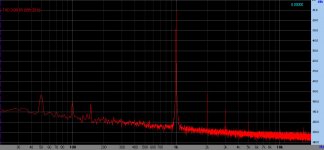
Sample: on of my #26 measuring.
The 60Hz component is relatively high, and sidebands is visible around the 1kHz base and harmonics.
Each #26 (01a are less) preamp is hum sensitive.
1.) The tube itself very sensitive to radiated hum, varies from piece to piece (even 10-15 dB difference occurs).
2.) The filament biased construction is sensitive, the non inductive bias resistor capable behaves like antenna.
3.) If you have unsatisfactory separation from anode supply (R or choke load), the 100/120Hz hum is appears.
In your case the primary source of hum maybe the tube (try to temporarily shield it with grounded aluminium foil), or the fialament bias resistor.
BTW try to decrease measured voltage to -10dB level.
Each soundcard tend to distort at +20dB.
Sample: on of my #26 measuring.
Attachments
Yeah, I noticed that, and I should've done a loopback measurement and subtracted it out from the main measurements. I believe the environment itself is noisy because I've seen that on other things I've measured. Will do the loopback and report back.
The RME is not clipping the input because I can monitor it. The input to the preamp is a little less than 1.0 V. The input into the ADC is -3.0 db below full scale.
But the sidebands are there. Thanks for the suggestions. Will check.
Which 26 tubes are you using, transformer-coupled? And operating point?
I should add: absolutely no hum is audible at the speakers.
Last edited:
Thanks! Wow, you have an order lower distortion with nearly the same setup. I do have the source follower, whereas you have a transformer that must be pretty transparent at 1 kHz.
Here's a couple of measurements:
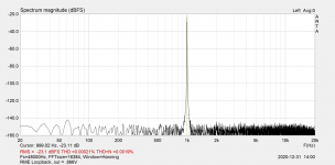
1. RME loopback. Output is at -3 db (0.866 V). This is at the lowest gain setting on the RME. It can actually swing quite a bit of volts at full gain.
2. Measurement with amp on and input at -120 db.
So, looks like the 60 Hz pickup is real. It is not at the speakers but it would be good to eliminate it and get rid of those ugly sidebands.
Here's a couple of measurements:
1. RME loopback. Output is at -3 db (0.866 V). This is at the lowest gain setting on the RME. It can actually swing quite a bit of volts at full gain.
2. Measurement with amp on and input at -120 db.
So, looks like the 60 Hz pickup is real. It is not at the speakers but it would be good to eliminate it and get rid of those ugly sidebands.
Attachments
My #26 preamp.
Hi Euro21,
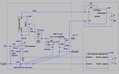
How is your cascode CCS built?
Do you have a schematic handy?
Thanks for your advice.
Best,
John
Here it is with aluminium foil around the tubes grounded to the chassis. Nice clean-up. Isolating the resistors will be difficult and will need them to be laid out again. I'll try tomorrow to get see what different operating points do with the foil in place.
Attachments
Here it is with aluminium foil around the tubes grounded to the chassis. Nice clean-up. Isolating the resistors will be difficult and will need them to be laid out again. I'll try tomorrow to get see what different operating points do with the foil in place.
Looks good but THD are measured with dBV not dBFS...
All the best for the new year 2021
Sorry, wrong value. I meant 100 - 220 ohm in parallel to filament bias resistor for a bit higher Ia.... or higher Ia by adding 10 - 22 ohm in parallel to the filament bias resistor.
That makes sense. I get what you're saying now. Might give that a try to see what happens at different grid to cathode voltages.
I've torn it down for now to improve a few things. It was a hot mess that I really wanted to listen to, but now that the itch has been sated, I can calmly work some more on it.
I've torn it down for now to improve a few things. It was a hot mess that I really wanted to listen to, but now that the itch has been sated, I can calmly work some more on it.
Signal chassis layout and induced hum
Hello all,
I have just reworked the layout on the signal chassis of a 2p29L preamp, and am now getting hum that wasn’t there before. The hum is not very loud, but it is audible and common to both channels.
The reworking occurred because I was trying to chase down some oscillations which ended up to be a bad tube.
Preamp is based on my previous 01a chassis and uses Rod Coleman Filament regulators and Ale Moglia’s hybrid mu-follower (aka gyrator) boards.
The only things that were changed were the layout, moving the Filament regs and Gyrator boards closer to the tubes (and closer to each other) in a more compact 3 dimensional layout. (See image)
There was, also, an increase in gate-stopper value on the gyrators lower fet from 330R to 1K.
The grounding scheme remains the same.
I added an aluminum “bridge” which serves as a heatsink for the filament regs and a support for the gyrator boards. The gyrators are secured at the corners with little stand-offs made from tiny stacked squares of double-stick foam tape and there is no ground connection made between board and chassis at the securing points. (That is to say that the resistance measures as open line between the boards and the aluminum bridge.)
The output caps sit below the gyrator PCBs under the bridge.
The original layout had the filament reg boards further away from the tubes—nearly 200mm which is Rod’s suggested max distance. I thought moving them closer would eliminate some noise, but...
It would be easy enough to return everything to the way it was, but I thought it would be informative to understand what is reacting with what here, in order to avoid this in the future.
Any ideas?
Thanks, as always for your help!
Best regards,
John
Hi Euro21,
Thanks for your response!
Yes the cap-casing and “bridge” are isolated.
I tried grounding each one individually and all together, but there was no change.
The socket and the center-tab that connects to the tubes outer shield are grounded. This is the same as it was before the new layout, the same as before the hum started.
Best,
John
- Home
- Amplifiers
- Tubes / Valves
- #26 pre amp