With 126C you might parallel primary and secondary for use as plate choke.
Nothing would change wrt to inductance, but DC resistance would be halved; that's never bad.
Did you try and measure the series connection of 126C??
Hi Pieter - that's another idea to try. Thanks! I didn't measure anything - just listened. The treble drop in series was quite substantial.
With 126C you might parallel primary and secondary for use as plate choke.
Nothing would change wrt to inductance, but DC resistance would be halved; that's never bad.
Did you try and measure the series connection of 126C??
how come ??
unless this is made by aliens.
I just tried 10Y into both a single 126C and two 126C in series used as plate chokes, just primaries used. FT-2 coupling caps. Conclusion was that two in series is definitely better. This gives 200H and the gains are in clarity, timbre and treble air and presence. Certainly worth the extra modest outlay.
This would no doubt be the same for the 26 so that's an idea for a plate choke. I previously just tested the 26 with a single 126C but I'd expect the same gains with two in series.
However, I just tested out a different plate choke with the 2P29L and that's as good as the 10Y with two 126C, maybe even a tiny touch better. So next is to try it with 10Y and see what that gives. There's no markings on it so I don't know the value, make or anything. I'll see if I can take a photo.
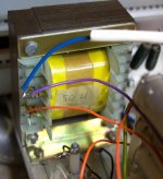
My other plate choke is marked 750R and 50H - sounds great with a 2P29L (Ra 3K) but a little flatter with a 10Y, it doesn't sound quite comfortable with its higher Ra of 5K-ish.
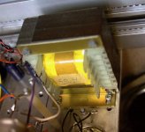
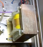
I'd like to know who made this plate choke - looks quite generic but maybe someone knows. I think I got it off Thorsten Loach around 10 years ago. Measures 80x65x55mm
I'd like to know who made this plate choke - looks quite generic but maybe someone knows. I think I got it off Thorsten Loach around 10 years ago. Measures 80x65x55mm
Attachments
how come ??
unless this is made by aliens.
That's actually correct as the windings are in parallel, the resistance is halved, but the inductance doesn't change. Magnetically it is equivalent to substituting a single larger piece of wire because the number of turns on the core has not changed. Connecting them in series would give you twice the number of turns, twice the DCR and four times the inductance.
I see that many uses quasi-choke input filters for B+ with a very small capacitor before the first choke. What are the advantages of using this little capacitor?
With no capacitor, the instant when the rectifier output is at (or near) zero can produce a rough waveform from the effect of leakage inductance and stray capacitance. A carefully chosen value can remove the roughness, without increasing the dc output. If possible, use this value.
Raising the value such that the dc output increase has the drawback that load-regulation is degraded.
I just built a choke input power supply for 845s with 750-0-750v transformer. The rise in DC output between 0.47uF and 1.0 uF is quite steep. 670v rising to 770v. Although 770V is nearer what I want I am wary of using this method to adjust the B+. PSUD2 doesnt show instability but it does seem like you would not want to be on that slope. Is it unstable as it looks?
Yes, the steep slope of Vout vs. C1-value is the problem.
It also means that if 670V is the dc-output with 470n, if you use 1µF and measure 770V, the dc-voltage will vary with load-current, much more than is the case with 470nF. This may be OK, depending on the rest of the design. Monitor the dc output for a while.
I would not expect instability (of the rectifier-current), unless the cap is around 220n, or lower.
The cap should be rated for 1000V ac, and/or 1.5/2kV DC.
I guess the DC slope doesn't interact with the signal due to the filter time constants, but it's scary stuff with high voltage choke input. Ideally everything needs to be rated to the full zero current B+ voltage. It can get out of hand setting bias up. I have some 0.5uF Dublier 1kV ac 1500V dc caps for the job. But have 800V 60uF pp following it. They make such neat little pp caps now, for solar apparently. BTW the Coleman fil regs are great and hardly get warm.
martin
martin
Is there anybody who has experienced a tiny spark in the AZ1 rectifiers? I have a LCLCRC filter followed by a Salas SSHV2. Weiss power transformer, hybrid bridge (AZ1 and UF4007) - 20 H choke (165 ohm) - 47uF - 5 H (65 ohm) - 47 uF - Resistor (47 R) - 300uF. The Salas draws 40mA. I can't see anything wrong when I do a simulation in the PSUD II. I should add that the tiny spark doesn't show itself everytime, but always in one section a few seconds after I turn on the amplifier. I can reduce the size of the first two capacitors, but NOT the last as it is two Black Gates in super-e that just sounds too fabulous. Should I add resistance on both plates or is it a faulty tube? Or perhaps something else?
Last edited:
- Home
- Amplifiers
- Tubes / Valves
- #26 pre amp