Absolute polarity is not something to be concerned about. Different recordings and even different tracks on the same album may have different absolute polarity. There's certainly no guarantee that all the microphones on a given track are in phase, and if you use a multi-way speaker, some of your drivers are probably out of phase relative to others!
Lots (I would say most) of tube preamps invert, don't sweat it.
Lots (I would say most) of tube preamps invert, don't sweat it.
Absolute polarity is not something to be concerned about.
Do you mean we can connect one speaker + to +, - to - ; while with the other speaker we can connect + to -, and = to + ???
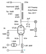
I posted this on another thread, but I'll post it here as well since the design should work for a 26 preamp. This is my new 10Y preamp. This supersedes all DHT preamps I've ever made (quite a lot) - more clarity, more neutral, better bass. It just sounds completely smooth and natural. Quite a big increase in clarity, in fact. I find myself listening at lower volumes since it's all so clear.
The Hammond 126Cs seem to be working well in series. A pair of these is cheaper than the Lundahl plate chokes, and I imagine just as good from my memories of a pair of Lundahls I once had. The Hammond are bifilar wound - one of their better products. I take the end bells off and mount them under the chassis. You just need the primaries. They're big and solid items. With 212H available, a pair in series should also work for a 01A or 26. Coupling caps are two FT-2 0.1uF in parallel, or you could use FT-3.
I'm very happy with this preamp - it's not going anywhere. I use a separate choke input filament supply and a separate PSU. Three chassis. Apart from the 10Ys themselves, it's not too expensive to make, though there's quite a lot of work in it. With a 26 it would be an economical option. I haven't heard it with a 26 but I'd be optimistic from what I'm hearing.
Attachments
https://frank.pocnet.net/sheets/049/1/10Y.pdf
According to the datasheet above, a 10Y typical operation points are at 250-350V and 45 ma.
Interested to know if you are using the 10Y as if a 10 (VT-25) with same results as in SQ ??
Cheers,
King
According to the datasheet above, a 10Y typical operation points are at 250-350V and 45 ma.
Interested to know if you are using the 10Y as if a 10 (VT-25) with same results as in SQ ??
Cheers,
King
10Y typical operation points
... in class C!
This is quite different operating mode than usually used class A.
As I wrote you later, 10Y working well in 200-250V 12...25mA region.
I prefer larger (20..25mA) anode current, but 12mA also usable.
No. You can:Do you mean we can connect one speaker + to +, - to - ; while with the other speaker we can connect + to -, and = to + ???
1. Connect both speaker + terminals to amplifier - and both speaker - terminals to amplifier +.
or
2. Connect both speaker + terminals to amplifier + and both speaker - terminals to amplifier -.
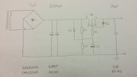
Something like the attached Rod?I like the Infineon & Wolfspeed SiC rectifiers, too. They allow a power-amp build with large, high quality capacitors.
I removed the LCLC supply from my power amp, and installed SiC rectifiers -Wolfspeed C4D02120A - and large capacitors ( 820µF 550V Kemet ALS60) x2 per channel. After these, a capacitor-multiplier (using large N-channel FET FQA9N80C), followed output capacitor LCR 30µF 630V FP-AU.
Superb sound. The cap-multiplier can be configured to gently ramp the supply voltage, too.
Q1 - I couldn't find a FQA9N80C, but I presume FQA9N90C is similar but 900V?
D1 - 1N4007 to prevent the drain swinging below the gate
R1&R2 - divider to set the gate below the drain (as the gate draws very little current there will be little voltage drop across R3). Say 10k and 470k.
R3 - gate stopper, say 47k
C1 - say 100uF
D2 - zener to prevent the gate swinging more than the maximum allowable gate to source voltage (in the case of Q1 30V), say 12V
Am I anywhere close?
Attachments
Something like the attached Rod?
Q1 - I couldn't find a FQA9N80C, but I presume FQA9N90C is similar but 900V?
D1 - 1N4007 to prevent the drain swinging below the gate
R1&R2 - divider to set the gate below the drain (as the gate draws very little current there will be little voltage drop across R3). Say 10k and 470k.
R3 - gate stopper, say 47k
C1 - say 100uF
D2 - zener to prevent the gate swinging more than the maximum allowable gate to source voltage (in the case of Q1 30V), say 12V
Am I anywhere close?
Hello Simon,
Yes, that's the kind of approach. I will offer some design notes.... I had better find the schematic.
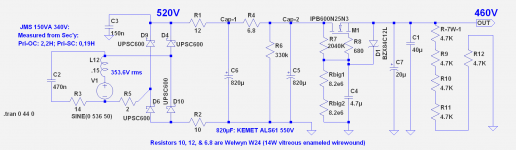
1. R1, R2: the rectifier should be protected from excessive power dissipation and/or current pulses at startup, and heavy load. Yes, even the C4D02120A SiC rectifiers can be damaged, if precautions are not taken in supplies with large-value capacitors. I prefer to keep the repetitive peaks (at startup) below 8A, and the values shown for R1, R2, and the equivalent for your transformer (R5 is this circuit) give this limit.
2. R4: decouples the recharge pulses from C1, and helps keep traces of these away from the final output.
3. C5,C6 are the big Kemet ALS61 820µF 550V caps.
4. R7; Rbig1, Rbig2 are the divider network to set the output voltage. The divider drops at least 10% of the supply voltage, to guard against sudden drops in the input voltage. The leakage current is low enough for 2MΩ to be used here, in practice: provided C4 is rated for 630V and a high-quality MKP. Rbig1 & 2 are high-voltage parts, or you can make up the value with a series of ordinary parts. But professional metal film parts should be used here - no carbon film, oxide etc. or the output voltage may drift.
5. R8 is the gate stopper. 680Ω shown, and should not exceed 1KΩ for high-voltage work: otherwise coupled-pulses from the drain may turn-on the FET, under some conditions. High values are not required for stability.
6. D1 is a BZX55C12 zener, the only required gate protection. I mount them on the far side of the gate stopper - to minimise the amount of metal that might couple the gate and drain directly, and reduce risk of oscillation. The zener lead passes over the FET drain lead, so this is not an idle comment. But don’t probe the gate directly (scope/DMM), if you do it my way.
7. Load resistors: I like to run some constant current through the output of the FET. 20mA in this case. It keeps the output impedance lower, drains the caps quickly, and offers somewhere for any returned energy to be absorbed.
8. Heatsink: try to select a sink that will keep the temperature rise below about 30°C.
The values are for a 300B-SE channel. You can use similar working for lower current, if you want to use it for a DHT preamp, but actually I might prefer a shunt regulator for that.
Attachments
Thanks Rod, that's really helpful. There's a little more to it than I had - it's getting in to Spice territory now (I really must learn how to use it one day).
A few more questions if I may.
Why are R1 and R2 dissimilar? And do they tend to make the PS "choke" input rather than cap input? Is R6 there to draw minimum current to force it in to choke input? EDIT - er, no, R6 isn't drawing much current at all.
Presumably R4 makes it a sectioned RC filter?
R7 and Rbig could within reason have a pot between them to offer some adjustment of output voltage. Or at least to help set the value of the resistors?
Does C7 need to be close to the output of the FET? Could it be in a separate chassis for instance? Or is it better to keep it with the cap multiplier and put C1 in a separate chassis?
Sorry for so many questions. The real benefit of this looks to be for output valves at higher current levels, I'd agree a shunt reg might be more interesting at lower pre-type currents. As it's not a reg per se, presumably there could be benefits having separate cap multipliers after the 2 big 820uFs for driver/channels? Apart from heatsinks and C1 there's not a lot of cost in the cap multiplier part.
Last edited:
Hello Simon,
R1 & R2 can be chosen to be the same, or different. R2 is at Ground on one end, so a scope clipped across it gives the recifier current, and 10Ω gives 10V per Ampère there - useful for verifying that the diodes are not over-stressed.
R4 is a RC filter, yes.
Yes, can add a pot to the voltage-setting divider string, but keep the voltage across it well below the pot's rated voltage.
Good question about separate chassis for PSU. In this case, everything up to the second big cap [C5] goes on the Transformer/PSU chassis.
The rest goes on the signal chassis - but with a 2-chassis layout: please add another capacitor, identical to the output cap (example: 30-40µF 630V Audio MKP, or DC-link) on the DRAIN (input-side) of the FET. These two caps should have a short wiring loop around them and the FET itself. Long wires risk adding enough inductance to make a Colpitts oscillator (if the source wire has most inductance) or a Hartley oscillator (if the Drain wiring is longer). Thus, the caps reduce the risk of instability of the cap-multiplier, but they must be wired tightly, to work correctly.
The output cap C1 should also be wired close to the load.
Well, my most recent preamp was a 10Y with 2 x Hammond 126C interstages in series, just used as plate chokes with Russian teflon FT-2 output caps. It sounds great.
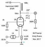
But it has a competitor now - I just built a 26 preamp with a single 126C as plate choke with FT-2 coupling cap. You may have gathered by now that I like the 126C a lot as a plate choke. I think I must have tried this setup as long as 8 years ago, but it's come up fresh and very nice this time. I run it at maximum for the 26 according to the data sheet to get the Ra down and give me as much current as possible to drive my 4P1L PSE output stage. OPT this time is O'Netics and I'm enjoying the sound a lot - it's full and warm yet still detailed. It's staying in my system for now - the 26 magic has come back.
It's a cheap build - 26 are plentiful and the Hammond 126C is very economical for what it is - a good bifilar wound transformer. You get 1:1 so no step-down. It needs to go straight in to the following stage, which in my case it does fine.
Attachments
- Home
- Amplifiers
- Tubes / Valves
- #26 pre amp