update
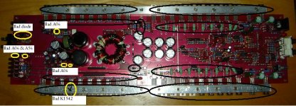
Ok, so I replaced all the parts in YELLOW in the attached picture. And retested to the best of my ability the circled parts in BLACK again. After test it seems I still have a problem. I have not yet powered it up because I feel it will cause more damage.
Results....
The ohms reading on all the 3205 seems be good now (~84 ohms) on all of them both sides.
But the 3205 seem to have continuity between all of then and pins 1&3, 2&3, & 2&1. Is this normal?
There seems to be a really high resistance between the positive and negative power terminals. This is not normal in my opinion.
So now I stuck. Any ideas an what to test and or replace next?
Thanks for your help, Sean
Attachments
But the 3205 seem to have continuity between all of then and pins 1&3, 2&3, & 2&1. Is this normal?
**** How many ohms?
There seems to be a really high resistance between the positive and negative power terminals. This is not normal in my opinion.
**** Initially, an ohm meter will read relatively low resistance but the readings will increase as the capacitors charge. This is normal. If there was low resistance all of the time, the amp would constantly draw current from the battery.
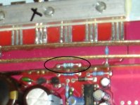
I'd expect to see ~110 ohms. They typically use a 100 ohm pulldown resistor but maybe they used a 75 ohm resistor in this amp. Do you see a 75 ohm resistor that's connected from the non-gate side of the gate resistor to ground?
You can power it up but clamp ALL transistors tightly to the heatsink and insert a 15 amp fuse in the B+ line.
You can power it up but clamp ALL transistors tightly to the heatsink and insert a 15 amp fuse in the B+ line.
Perry,
So I put everything back together and tried to power it up. It blew a 10 & 15 amp fuse. I have about 120 ohms between the positive and negative power terminals. I don't think this is normal.
Can you please provide a picture to your question, "Do you see a 75 ohm resistor that's connected from the non-gate side of the gate resistor to ground?".
I think my reading of ~84 ohms on the 3205s is normal on pin 1&3 because I get the same reading on my working amp.
So now I really stuck. Not sure what to do next. Please help.
Thank for your time,
Sean
So that we're not chasing a problem that doesn't exist, check the good amp and make sure that the resistance across the power terminals (red lead on B+) goes into the thousands of ohms.
Also confirm that the resistance from the B+ terminal to the shields is in the k-ohm range.
Do you show anything near 0 ohm continuity from the tabs of the transistors clamped to the sink and the heatsink?
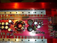
Can you send me 8-10 photos of the top and bottom of the board at the highest resolution possible? If so, take them from all angles (turn the board 90° for each new photo).
babin_perry@yahoo.com
Also confirm that the resistance from the B+ terminal to the shields is in the k-ohm range.
Do you show anything near 0 ohm continuity from the tabs of the transistors clamped to the sink and the heatsink?
Can you send me 8-10 photos of the top and bottom of the board at the highest resolution possible? If so, take them from all angles (turn the board 90° for each new photo).
babin_perry@yahoo.com
Perry,
On the bad amp.....
Continuity from the tabs of the transistors clamped to the sink and the heatsink?
Power side = 84, 130, & 0.3 ohms on pins 1, 2, & 3 (might be backwards, not sure what the order is).
Sound side = 1.0, 720, & 1.0 ohms on pins 1, 2, & 3 (might be backwards, not sure what the order is).
If you have 0 ohms across the B+ and ground terminals of the 'good' amp, it may not be as good as you think. That would cause it to blow the B+ fuse the instant it was connected.
None of the audio output transistors should show near 0 ohms to the heatsink. Unclamp them, lift them slightly and recheck the resistance to the sink.
None of the audio output transistors should show near 0 ohms to the heatsink. Unclamp them, lift them slightly and recheck the resistance to the sink.
Perry,
On the good amp, if I probe my meter (Fluke 77) to the pos. & neg. terminals I get = O.L If I reverse the polarity I get -2.8 ohms.
I beleive my 3rd amp gets a simular reading and its a 225 HCCA.
Both my good amps are working fine and I use them every day(w/ a 60 amp fuse, each).
If I unclamp them, lift them slightly and recheck the resistance to the sink.... If there not clamped then of course the resistance will be 0. Am I missing something? If there not in contact then no resistance, right?
Uploading pictures right now.....Sean
OL and -2.8 is not near 0. The -2.8 is caused by having charged capacitors. The OL means there is no significant current flowing out of the meter into the circuit.
If you lift them from the sink, you should read OL or something in the thousands of ohms (depending what else is still clamped to the sink).
If there is no contact the resistance should be near infinity (open connection). If there is a short circuit, you would read something near 0 ohms.
If you lift them from the sink, you should read OL or something in the thousands of ohms (depending what else is still clamped to the sink).
If there is no contact the resistance should be near infinity (open connection). If there is a short circuit, you would read something near 0 ohms.
- Status
- This old topic is closed. If you want to reopen this topic, contact a moderator using the "Report Post" button.
- Home
- General Interest
- Car Audio
- 250 hcca grounded out problem