Insert a 5 amp fuse in the B+ line and power the amp up for a few seconds out of the heatsink. Does the fuse blow?
The power LED won't light up. Make sure that the wires that you desoldered are not in contact with the board or the other wires.
OL on those wires means it's not shorted to the primary (a good thing).
The power LED won't light up. Make sure that the wires that you desoldered are not in contact with the board or the other wires.
OL on those wires means it's not shorted to the primary (a good thing).
There are two diodes between the windings you desoldered and the filter capacitors. Desolder the outside legs of those diodes and lift them. Apply heat from the top of the board.
Go back to the two large rectifiers with your meter set to diode check. Do you get ~0.35v one direction and a stead climbing reading with the probe reversed?
Go back to the two large rectifiers with your meter set to diode check. Do you get ~0.35v one direction and a stead climbing reading with the probe reversed?
My bad, my meter dose not show units on diode check.
So I placed the neg. probe on the neg. power terminal and the pos. probe on the pin 3.
Results.....
Power side = all 0.6-0.9 ohms
Output side = all of the right half top and bottom = -0.7 ohms
= all of the left half top and bottom = 1.4 ohms
Thanks,
Sean
So I placed the neg. probe on the neg. power terminal and the pos. probe on the pin 3.
Results.....
Power side = all 0.6-0.9 ohms
Output side = all of the right half top and bottom = -0.7 ohms
= all of the left half top and bottom = 1.4 ohms
Thanks,
Sean
What do you mean by "Output side = all of the right half top and bottom"?
Just to make sure we're on the same page...
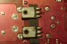
When you say pin 3 of the audio output transistors, do you mean the legs indicated by the black arrows?
Is the point indicated by the orange arrow the chassis ground terminal you're using?
Just to make sure we're on the same page...
When you say pin 3 of the audio output transistors, do you mean the legs indicated by the black arrows?
Is the point indicated by the orange arrow the chassis ground terminal you're using?
Attachments
Perry,
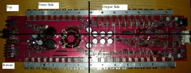
I have attached a picture to explain what I mean about top and bottom, power side and output side. Hope this clears some things up.
Yes my meter reads ohms w/ a "M"
I measured again and findings are a little different.....
Botom output side all = ~1 ohm, but the last one = -0.67 ohms
Top output side all = ~ 0.7 - 0.9 ohms, but the last 2 = 4.4 ohms and -1.6 ohms
Yes the neg. probe is in the right spot (organge on your attachment) and I am probing pin 3.
Thanks again,
Sean
Attachments
- Status
- This old topic is closed. If you want to reopen this topic, contact a moderator using the "Report Post" button.
- Home
- General Interest
- Car Audio
- 250 hcca grounded out problem