The resistor can be anything 1/8 watt or larger (doesn't need to be larger than 1/8w). Get several in case you break it.
The pot isn't critical but it will be easier to work with if it's a shaft-type pot (instead of a trim-pot). When soldering the wires on it, don't let solder drip back into the pot.
I'll post the procedure and a couple of photos in another post.
The pot isn't critical but it will be easier to work with if it's a shaft-type pot (instead of a trim-pot). When soldering the wires on it, don't let solder drip back into the pot.
I'll post the procedure and a couple of photos in another post.
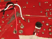
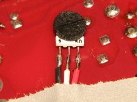
Connect the pot across B+ and ground. In the photo, the red wire is connected to B+. The black wire is connected to chassis ground. Connect the 15k resistor between the wiper (white wire) and the base (leg 1) of the regulator transistor (2N6488 standing in power supply). Turn the pot fully clockwise so that you have full B+ on the wiper.
Connect the black probe of your multimeter (set to DC volts) to the RCA shields. Connect the red probe to one of the emitter resistors.
Connect the B+ (fused) and ground. With the pot fully clockwise, confirm that you have full B+ voltage on the resistor (the end not connected to the regulator transistor).
Apply remote voltage and SLOWLY turn the pot counter-clockwise. You will eventually see the DC voltage increase (will increase quickly at some point). Continue turning until you get to ~±35v on the meter. If it's difficult to maintain precisely 35v, set it to ~30v so you don't accidentally go over the rail cap rating.
Does the fuse blow?
If so, at what voltage does it blow?
Does the amp now produce audio with the rails at ±35v?
Have everything clamped to the heatsink and have a 10 amp fuse in the B+ line. You should be able to make all of the connections without removing the board from the sink. You'll have to resolder the secondary windings on the board.
Attachments
Last edited:
Perry,
I'm working on this set up as we speak. I do have a few questions.
When you say connect the black wire to chassis gound. Can that be the neg. power terminal?
Also, won't this blow the as soon as I power it up? Whats the difference? Am I missing something. It seems that this set up is regulating the voltage but the voltage is already there.
Thanks,
Sean
You can connect the black wire to anythign that reads 0 ohms to the ground terminal of the amp. I don't really like using the term 'negative' for the chasss ground because it's at 0v, it doesn't have negative voltage on it.
With the pot initially set as I described, the power supply will be shut down. As you turn it counter-clockwise, it will begin to allow the voltage on the audio section to increase.
With the pot initially set as I described, the power supply will be shut down. As you turn it counter-clockwise, it will begin to allow the voltage on the audio section to increase.
If you have the pot set as I suggested, it won't blow a fuse. You have to have power connected to the amp (no remote) to check the voltage on the pot. When you apply remote voltage, it should no longer blow the fuse (until, possibly when begin to turn the pot counter-clockwise).
- Status
- This old topic is closed. If you want to reopen this topic, contact a moderator using the "Report Post" button.
- Home
- General Interest
- Car Audio
- 250 hcca grounded out problem