There are dozens of posts, maybe even approaching hundreds, telling you that this does not work.I use current mirror on both side of the LTP
It seems to have originated in a Sloan/Slone book and got copied by many.
Cordell and others have shown how to keep the mirrors and ensure correct operation.
The easier solution is to use resistor collector loads for all four LTP transistors.
There are dozens of posts, maybe even approaching hundreds, telling you that this does not work.
It seems to have originated in a Sloan/Slone book and got copied by many.
Cordell and others have shown how to keep the mirrors and ensure correct operation.
The easier solution is to use resistor collector loads for all four LTP transistors.
Thanks for the last post, I am just too busy to work on that just yet.
Not just Cordell. I am studying the paper on distortion by D Self. He also a big advocate for current mirror on the LTP.http://www.douglas-self.com/ampins/dipa/dipa.htm
The reason for the mirror is increase the gain of the first stage when using degenerate emitter resistor( described in Cordell) on the differential pair transistors. It is very very important to have the degenerate resistor for 1) linearize the gain, 2) decrease offset error that Self described is very important to lower distortion.
Like in my design, I use 300 ohm resistor, it I use a collector resistor of 1K, the gain of the IPS is only going to be 1000/326= 3!!! By the way I use 3 transistor current mirror, the gain is set by the 47K resistor for LF.
Yes, I know at HF, gain is set by the Zmiller/RE, but you need high gain for LF to lower distortion at LF.
I am very familiar with this type of general design as I spent a few years designing bipolar analog ICs that had opamps. All these make sense, not just blindly follow what the book said. In fact, I am actually considering spending the money to put in matching transistor pair for the LTP to lower offset and matching current. This is only one of the design, I am going to design something similar to Apexaudio with single LTP as IPS, but using precision matched transistor and emitter degeneration resistors to keep the distortion down. I really like the Apexaudio's design. This one is just more Cordell's suggestion.
Last edited:
Why doesn't it work? Cordell explained very clearly in page 139, Fig. 7.10 how to establish bias voltage.Long response but no mention of the FACT that a mirror loaded dual complementary LTP does not work !
FYI, Fig.33 in "Distortion of Power Amplifier" by D Self gives a very good explanation how to lower distortion on the Blameless Amp. Those happens to be what I designed into my circuit before I even read this.
Last edited:
Long response but no mention of the FACT that a mirror loaded dual complementary LTP does not work !
A Taxonomy of Help Vampires - jasonwryan.com
and your message is?
or are you simply straying "off topic"?
Cordell explains WHY it does not work.Why doesn't it work? Cordell explained very clearly in page 139, Fig. 7.10 how to establish bias voltage...........
This Forum has explained many times WHY it does not work.
Cordell went to some lengths to explain how to MODIFY the topology to get a working version that retains the mirror loading
That adds a lot of complication.Cordell and others have shown how to keep the mirrors and ensure correct operation.
Instead you can simplify
Your existing sch has the same errors as the Sloan/Slone proposal. It will not work.The easier solution is to use resistor collector loads for all four LTP transistors.
No it is not. Look again. Sloan schematic does not work. It is very obvious as nothing is done to set the current of the VAS. But my circuit works. You are arguing about Fig. 7.9 in Cordell's book, not Fig.7.10.
I post this question to Bob Cordell's thread in SS. You are welcome to join in.
I post this question to Bob Cordell's thread in SS. You are welcome to join in.
Please read this http://www.diyaudio.com/forums/solid-state/171159-bob-cordells-power-amplifier-book-498.html
Starting from post #4977 on. Mr. Cordell replied. I made my case in post #5004. My design is very different from Sloan( that absolutely does not work). I use huge emitter degeneration to get the stability.
http://www.diyaudio.com/forums/solid-state/171159-bob-cordells-power-amplifier-book-498.html
Starting from post #4977 on. Mr. Cordell replied. I made my case in post #5004. My design is very different from Sloan( that absolutely does not work). I use huge emitter degeneration to get the stability.
http://www.diyaudio.com/forums/solid-state/171159-bob-cordells-power-amplifier-book-498.html
I am familiar with R.Cordell's book.
I am familiar with LTPs.
It appears I am not familiar enough with the modifications required to get the dual complementary mirror loaded LTP to work.
But you seem to have eventually solved your problem.
I just avoid the problem, the "simple" way. i.e copy Leach if I want a dual complementary LTP or copy J.Curl for a jFET version. Both use resistor loading.
You are absolutely right!!I am familiar with R.Cordell's book.
I am familiar with LTPs.
It appears I am not familiar enough with the modifications required to get the dual complementary mirror loaded LTP to work.
But you seem to have eventually solved your problem.
I just avoid the problem, the "simple" way. i.e copy Leach if I want a dual complementary LTP or copy J.Curl for a jFET version. Both use resistor loading.
I was so hoping that the circuit would work as it's in the book. But there is a serious problem from the simulation as I posted in the the last thread of the page:http://www.diyaudio.com/forums/solid-state/171159-bob-cordells-power-amplifier-book-504.html
I am so hoping I can fab the board and tweak as I go along. But I guess I have no choice but to stop and work on the LTspice to get another low distortion design. That circuit is too touchy to use.
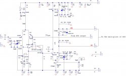
I am thinking about using a single LTP IPS as there doesn't seem to have a graceful way to use current mirror in the complementary IPS. Using Resistor load for IPS might create more distortion than it's worth to have the complementary LTP.
Attached is my new design, I still need to learn how to simulate distortion with LTspice to check.
Thanks
Attachments
Last edited:
Hi Alan(0354),
Now first I'd like to say that I haven't read more than just the last few posts in this thread so I hope my comments are relevant ... However, what reading these posts made me think of was if you have read Samuel Groner's analysis of the distortion mechanisms related to a circuitry - not entirely identical to yours - with similarity to yours? It's a comment to some of the circuitries found in Douglas Self's book on power amplifiers (with an analysis of distortion mechanisms).
There's a link here:
http://www.sg-acoustics.ch/analogue_audio/power_amplifiers/pdf/audio_power_amp_design_comments.pdf
Best regards,
Jesper
Thanks, I read this, I have to re-read again. One thing pops up is Self uses asymmetric VAS where one side is CCS. I read that this gives asymmetrical slew rate between rising and falling of the the waveform. I always wonder whether it will help if I increase the current of the CCS to more than 10mA. I am planning to use 3EF OPS, so the loading on the VAS should be very low.Hi Alan(0354),
Now first I'd like to say that I haven't read more than just the last few posts in this thread so I hope my comments are relevant ... However, what reading these posts made me think of was if you have read Samuel Groner's analysis of the distortion mechanisms related to a circuitry - not entirely identical to yours - with similarity to yours? It's a comment to some of the circuitries found in Douglas Self's book on power amplifiers (with an analysis of distortion mechanisms).
There's a link here:
http://www.sg-acoustics.ch/analogue_audio/power_amplifiers/pdf/audio_power_amp_design_comments.pdf
Best regards,
Jesper
My design is kind of like a modification of Self's circuit after I read it. I try to turn it into symmetric VAS. But I prefer not to have resistor load like Apexaudio SR200. So I came up with the idea of a single ended driving a LTP VAS as shown.
Thanks
Last edited:
Your latest has similarities to Symasym and Roender........................
I am thinking about using a single LTP IPS as there doesn't seem to have a graceful way to use current mirror in the complementary IPS. Using Resistor load for IPS might create more distortion than it's worth to have the complementary LTP.
Attached is my new design, I still need to learn how to simulate distortion with LTspice to check...........
Worth looking at both to see how they solved it.
ThanksYour latest has similarities to Symasym and Roender.
Worth looking at both to see how they solved it.
I'll look into that. It's kind of back to the drawing board.
- Status
- Not open for further replies.
- Home
- Design & Build
- Parts
- 220uF cap for GNFB