look up the data posted by Eva from nearly a decade ago.Do you have any article or thread talking about resonance when parallel two caps?
But the idea is the same, you want to keep the impedance low at high frequency to keep the closed loop gain constant, not going down. Amp can go into instability when closed loop gain reduce and high frequency.
Unfortunately many of his pics were not attached and links have died.
We still have not learned.
I want to use ceramic for the smaller size. The summing junction is the most critical point of the opamp and a big film cap can pick up noise.
Ceramic cpacitors are best avoided in signal path (except NP0 type which is not available in compact size) as they distort orders of magnitude more than electrolytic caps. You can use fine polyprop instead. You can also increase the value of the inner 24k9 resistors (DC connected to input nodes) to e.g. 100k which will allow for even lower cap values. Yet don't go too low (e.g.couple of uF) to avoid increased noise.
Last edited:
220uF with a 500r will not be low distortion at 20Hz.
The cap is seeing some AC signal voltage and will distort.
The break frequency of 500ohm and 220uF is 1.45Hz. It is over a decade lower than 20Hz. Distortion is more prominent around the break frequency.
Reactance of 220uF at 20Hz is j36ohm. So the two in series is 500+j36 and the magnitude of the series combination is sqrt{5002+362}=501.3ohm. The contribution of the j36 is very small. It is not as if you have 500+36=536!!!
You still have to look at the % deviation of the capacitance.
D.Self has published data showing the distortion rising above the noise floor way above the F-3dB of the RC.The break frequency of 500ohm and 220uF is 1.45Hz. It is over a decade lower than 20Hz. Distortion is more prominent around the break frequency.
Reactance of 220uF at 20Hz is j36ohm. So the two in series is 500+j36 and the magnitude of the series combination is sqrt{5002+362}=501.3ohm. The contribution of the j36 is very small. It is not as if you have 500+36=536!!!
You still have to look at the % deviation of the capacitance.
That does not exclude the increase in distortion that is below the noise floor.
We can hear artifacts well below the noise floor. Distortion may be some of the audible artifacts that our brain/ear can pull out from the signal.
Then we have a problem using 220uF bipolar electrolytics then!!! Then we are back to square one!!! So what are we talking about in this 5 pages if that's not good enough? Back to metal polypro?D.Self has published data showing the distortion rising above the noise floor way above the F-3dB of the RC.
That does not exclude the increase in distortion that is below the noise floor.
We can hear artifacts well below the noise floor. Distortion may be some of the audible artifacts that our brain/ear can pull out from the signal.
Putting an input high pass does not exactly solve the problem, you still need another cap that have the same issue.
I don't follow what you try to say. How do you put the input filter? Do you mean just a RC high pass filter at the input to attenuate the low frequency?As an example, I use ~90ms as the input filter.
That then fixes the NFB @ ~140ms and the PSU @ 160 to 200ms
That way neither the PSU, nor the NFB get exposed to significant LF stimulation.
This fits with "set the bandwidth limits" with the Input Filters.
As an example, I use ~90ms as the input filter.
That then fixes the NFB @ ~140ms and the PSU @ 160 to 200ms
That way neither the PSU, nor the NFB get exposed to significant LF stimulation.
It lowers LF eposure by <6dB (90ms vs 140ms), not that it completely eliminates it.
Yes, RC passive single pole filtering at the input to set the passband of the amplifier.I don't follow what you try to say. How do you put the input filter? Do you mean just a RC high pass filter at the input to attenuate the low frequency?
Then you have less signal across the NFB capacitor.
Low signal already ensures low distortion.
Less signal ensures even lower distortion.
see my new post.It lowers LF eposure by <6dB (90ms vs 140ms), not that it completely eliminates it.
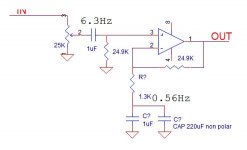
Thanks. I want to verify with you that's what you mean. Attached is the opamp with input RC high pass that has break frequency of 6.3Hz using 1uF and 25K resistor. The closed loop path has the 1.3K resistor and 220uF cap that gives the break frequency of 0.56Hz. This is one decade lower than the input HP filter.Yes, RC passive single pole filtering at the input to set the passband of the amplifier.
Then you have less signal across the NFB capacitor.
Low signal already ensures low distortion.
Less signal ensures even lower distortion.
It is easy to get a small metalized 1uF polypropylene cap for the input HP filter.
Thanks
Attachments
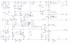
I just fixed it. It's updated.Your schematic is unreadable!
There should be blobs where wires join: I cannot tell if they are joins or crossovers.
Add RF attenuator at the PCB input.
Add a grounding resistor before the DC blocking cap on the input.
remove the 2k from the two CCS in the LTP tails.
Use another 4148, or use green led (green = ON/OK)
but red is possibly less noisy and lower dynamic impedance.
Very Leach Lo Tim !
You could adopt his CCS since you already have the Zeners and save about ten components.
Add RF attenuator at the PCB input.
Add a grounding resistor before the DC blocking cap on the input.
remove the 2k from the two CCS in the LTP tails.
Use another 4148, or use green led (green = ON/OK)
but red is possibly less noisy and lower dynamic impedance.
Very Leach Lo Tim !
You could adopt his CCS since you already have the Zeners and save about ten components.
Why a LED instead of 2K resistor to set the current? Is it for temperature compensation?
I looked a Leach Lo Tim. It's not quite the same. I use current mirror on both side of the LTP. Also, I use darlington VAS to increase input impedance. In fact, IPS and VAS of Leach is very similar to my Acurus. The major difference is Leach uses 3EF output.
I wonder why amps sound so different even if the circuit is so similar. Leach is well respected, my Acurus is only a so so amp!!! Is the 3EF that important?
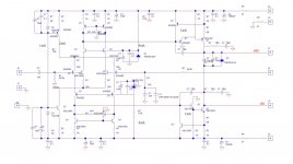
I updated the schematic and finished the layout. Here is the updated version with reference designators.Pity there are no device labels in the CCS area of the sch.
I could explain how your components affect the operation of the CCS.
But there isn't and so I can't.
The simple guide:
Sort the CCS so that it has a chance of achieving Constant Current.
I am reading Self's distortion of power amp paper. Looks like I did a few things right. I did not realize imbalance of the LTP IPS cause distortion. I put in the 300 ohm emitter resistor to linearize the transistor, that actually takes care of the imbalance to a great extend. Also the EF buffering of the VAS supposed to help.
Thanks
Attachments
Last edited:
look at the components Q24, R25, D69 & R28.
The current through D69 and R28 set up a voltage.
The current through Q24 base to emitter and R25 set up a voltage.
These two voltages MUST be EQUAL.
i.e. Vfd69 + Vr28 = Vbeq24 + Vr25
For constant current through the LTP, Q21 & Q22 the current through R25 must be held constant. This requires that Vr25 is held constant.
Vbeq24 is nearly constant, in that it hardly varies over a very wide range of Ie.
For CCS operation Vbeq24 + Vr25 should be held as near constant as possible.
Your Vr28 defeats this constant voltage requirement for CCS operation.
You must remove R28 and replace it with a near constant voltage device, i.e. a device that holds near constant voltage as current through D69 varies.
Replace R28 with a diode
or
replace R28 & D69 with a red, or green, LED.
OR
copy the Leach arrangement for CCS action using the Zeners you already have in the schematic.
Last edited:
- Status
- Not open for further replies.
- Home
- Design & Build
- Parts
- 220uF cap for GNFB