It's not 20 watts but at the moment I'm listening to a CF parafeed headphone amp based around a single compactron that'll swing 11 volts p-p into a pair of 60 ohms headphones and sounds wonderful. The only gotcha is it takes a lot of current to keep HF distortion in the ballpark of LF distortion due to the CF's asymetrical slew rates.
Did you gentlemen try such tubes like IRFP27N60K, or similar?
No, they don't fit any of my sockets! I can't see the glowing cathode too well either.
IRFP27N60K
Sure, the transconductance would be hard to beat and there wouldn´t be any heater-cathode insulation issues...
")
A mosfet follower with a low ratio OPT and a tube input stage would be very interesting.
Anyway, cathode follower obviously has certain qualities as output stages.
I have a pair of 3,5k/8 15W OPTs that I bought for the 808 project, now I´m getting curious how these would perform wired as 1,75k/8 driven by PL519 followers.
The transformers sounded quite good when i tried them in a tiny spud amp last weekend and they would probably sound even better with properly sized output tubes.
Gah, so many projects, so little time...
The only gotcha is it takes a lot of current to keep HF distortion in the ballpark of LF distortion due to the CF's asymetrical slew rates
Interesting point
Fuling said:
Sure, the transconductance would be hard to beat and there wouldn´t be any heater-cathode insulation issues...
...and there will be no need for an OPT!
I switched to them after experimenting with tube cathode followers. By the way, even ordinary power transformers sounded nice with cathode followers, auto-transformers even better, especially when the follower is loaded by CCS. A first, I used a MOSFET as a CCS. Then, I used it instead of a cathode follower. After that I replaced a CCS by a voltage to current converter made of pair of BJT's. That breadboard scared me when a water run on a record suddenly. I've jumped and turned around before realizing that there can't be a waterfall in my room...
Jeb-D. said:
Interesting pointThe only gotcha is it takes a lot of current to keep HF distortion in the ballpark of LF distortion due to the CF's asymetrical slew rates
...and absolutely valid one!
I switched to them after experimenting with tube cathode followers. By the way, even ordinary power transformers sounded nice with cathode followers, auto-transformers even better, especially when the follower is loaded by CCS. A first, I used a MOSFET as a CCS.
A CF on top of a mosfet CCS, cap coupled to an autoformer is something I´ll try someday.
Until then, the idea of a PL519 CF amp with my existing 3,5k (miswired to 1,75k) OPTs seems more and more appealing.
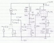
If done right it could be very minimalistic:
Interesting point
Yes, but I imagine that to get these kind of voltage swings we need fairly "grunty" driver tubes anyway.
Attachments
Fuling said:
A CF on top of a mosfet CCS, cap coupled to an autoformer is something I´ll try someday.
Until then, the idea of a PL519 CF amp with my existing 3,5k (miswired to 1,75k) OPTs seems more and more appealing.
Good luck, you are on your own Road To The Rome!
your own Road To The Rome
Considering the amounts of energy stored in the 320V 350mA PSU
this amp would require, I´m more likely on my own road to...hell.
I´ve been lucky with HV supplies so far, but I guess that when I finally get zapped it will be from a PSU capable of turning me into 300 pounds of roast beef in 3 seconds...
Fuling said:Yes, but I imagine that to get these kind of voltage swings we need fairly "grunty" driver tubes anyway.
Not exactly. The Rp of the CCS-loaded driver tube in the above application is over 50kohm and static current around 1 ma. Plate swing is about 120 volts p-p, not that much drive by CF standards. At these levels even a 20 kHz square wave at the input of the CF looks very good. The CF output however shows significant slewing in one direction, causing the waveform at max levels and high frequencies to go sawtooth in shape. Fortunately it's possible to balance output bias current against level and still get ~110 dB from the headphones at 10 kHz with under 0.1% second harmonic distortion. If that's audible, it won't be for long. The output stage of this little HP is running 40+ ma to achieve that!
Fuling said:
Considering the amounts of energy stored in the 320V 350mA PSU
this amp would require, I´m more likely on my own road to...hell.
I´ve been lucky with HV supplies so far, but I guess that when I finally get zapped it will be from a PSU capable of turning me into 300 pounds of roast beef in 3 seconds...
Much less than 300 pounds... Liquid evaporate, fat burn.
rdf: You´re right, we don´t need much of a driver tube to get 120V p-p. 1mA is much less than any plate current I´ve ever operated any tube at. I have this thing about high current, low Rp drivers...
Wavebourn: 300 pounds is what would be left after the evaporating and the burning... No, I´m kidding of course!
By the way, there seem to be some confusion about the specs of my output transformers.
I bought them on Ebay a year ago and the specs says:
3,5k
150mA
20W
2kg each
Another guy is selling transformers that looks exactly the same but are speced as follows:
3,5k
90mA
10W
1,75kg
Don´t know what to believe, what bothers me is the DC current rating.
If the transformers only can handle 90mA they might get a bit upset is I push 140mA through them...
No, they don't fit any of my sockets! I can't see the glowing cathode too well either.
One could compensate this shortcoming by applying Nelson Pass's technic of the Zen Lite, but instead use the filament of a valve to create the simple CCS. A GM70, with its 20V/~3A seems a perfect candidate for a small, SE SS amplifier
The GM70 is also cheaper than an 'equivalent' 0.5K/W heatsink (at Farnell prices for the heatsink) But, maybe it's not a bad idea for a bi-amped, hybrid system? Free heater power for the GM70, and some watts for a tweeter.
Erik
ErikdeBest said:
One could compensate this shortcoming by applying Nelson Pass's technic of the Zen Lite, but instead use the filament of a valve to create the simple CCS. A GM70, with its 20V/~3A seems a perfect candidate for a small, SE SS amplifier
But, maybe it's not a bad idea for a bi-amped, hybrid system? Free heater power for the GM70, and some watts for a tweeter.
Erik
It shall work!

But a filament is bad CCS, it is non-linear, frequency dependent, and dynamic resistance is low if to compare to a CCS made on a single transistor. Even a single transistor CCS will perform better.
But the drawback is, you will need too much of power to dissipate, i.e. idle current should be equal to a peak current, i.e. amplitude divided by a smallest possible impedance of the speaker in the frequency band. Also, current through the cathode (or source) follower will depend on output signal, i.e. on max negative polarity it will be minimal, no max positive polarity it will be maximal.
Voltage to current converter allows to select a compromise between 2 requirements:
1. High-end: idle current is equal to max output current. Current through the cathode (or source) follower is always the same.
2. Hi-fi: idle current is equal to half of maximal output current. Advantage over a plain CCS: less money will go to the company that provides electricity, smaller and cheaper heatsinks.
Here is the sketch:

You may see a paralleled FET and BJT follower (I call it Tango Pair) loaded by a current mirror output. The current mirror is controlled by a p-n-p transistor, which output current depends on a voltage on it's base. Very simple.
To get close to zero output DC offset I used a servo made on a single opamp.
About "Tango" pair: if you look at the input capacitance of MOSFET it may be seen as a varactor between driver and load. It may be shunted by resistor for less impact. Resistor may also provide clean zero-crossover current from driver to load, if it's value is small, and a driver is powerful. Also, the current may be provided by biased in class A emitter follower working in parallel with FET... This emitter follower may be degraded such a way with a resistor in emitter so it may supply current up to the region of beta droop, working always in small region of currents defined by Vgs of the FET. I call such couple "Tango", as if FET and BJT emitter followers dance helping each other...
Your choice: 20W cathode follower, or 200W Tango follower.
Your choice: 20W cathode follower, or 200W Tango follower.
Hi Wavebourn
Thanks for posting the schematic. I will have to digest that, may take some time, but I have lots of that available lately.
The idea of the GM70's cathode as CCS was not ment for real as a plain resistor is a bad CCS...it works, but with a maximum efficiency of 12,5% and probably way to much 2nd order distortion (not just to much, but waaaaay to much). And I had not even thought about the non linearities of the filaments resistance... GM70's are not up to neither my capacities (the GM70 is cheap, but all electronics around it aren't) nor capabilities (I would not dare to work with voltages around 1kV).
Erik
korneluk said:BTW, I still like the idea of a class A2 SE DHT cathode follower.
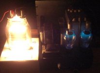
My two favorite kinds - blue mercury glow and thoriated orange glow. Just a little teaser shot before the holidays...
Attachments
- Status
- This old topic is closed. If you want to reopen this topic, contact a moderator using the "Report Post" button.
- Home
- Amplifiers
- Tubes / Valves
- 20W cathode follower amplifier