It took me a couple of hours to build the ugliest prototype known to mankind. I´ve seen and built ugly stuff before but this one plays in another league. Since I don´t want to make a complete fool of myself I won´t post any pictures...
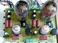
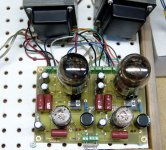
This is what´s going on: 300V B+, AC heating, 808 as cathode follower with a 3,5k OPT, IRFP460 source follower direct coupled to the 808s grid with a 10H choke and a resistor as source load instead of a negative supply.
No gain stage yet, but the night is still young...
One funny thing is that when I apply power to the filament a fairly loud hum is heard from the speaker and it disappears when I apply B+. There is still a buzzing sound which I assume is 100Hz ripple from the PSU, it doesn´t sound like the clean 50Hz filament hum. The humbucking pot across the filament seems to work as intended and would probably work even better on a properly layed out design, this prototype is a complete mess when it comes to transformer placement and wiring.
Just for fun I tried listening to some music by inserting a signal from my CDP to the gate of the mosfet (through a cap of course).
Without a gain stage it is of course impossible to say anything at all about the sound.
Next thing will be to add a triode input stage, 1/2 PCC88 will do for the time being.
I had a couple of similar hum experiences:
I built a conventional SE amp that hummed on power up then quieted down as the tubes warmed up. It turned out to be magnetic coupling from the power transformer to the OPT. Rotating the power transformer 90 degrees fixed it.
I did some ugly prototyping of my own with an 833A tube a few years ago, using AC on the filament (10 volts 10 amps). The amp hummed fairly loudly with only the filament of the 833A powered. There was nothing that I could do to quiet the beast, except for DC filament power. I used a 25 amp bridge rectifier and a large cap (don't remember the value). No regulator or other filtering was needed. A length of wire between the rectifier and cap served to lower the voltage and limit the peak current. Most hum disappeared.
I am away from home (and my notes) for the next 8 days with limited, slow internet access. I have already got some more cathode follower designs simulated in my laptop. The experimentation will resume in about 2 weeks.
It has happened to me before too when I was breadboarding an 6B4G SE amp.
I will run some more tests tonight with a regulated power supply borrower from my 807 amp, if it turns out that I can get the hum down to practially nothing then I´ll continue developing this cathode follower design. If not I´ll go for DC heating and a more conventional output stage design with some cathode feedback to "straighten out" the tube as much as possible.
I will run some more tests tonight with a regulated power supply borrower from my 807 amp, if it turns out that I can get the hum down to practially nothing then I´ll continue developing this cathode follower design. If not I´ll go for DC heating and a more conventional output stage design with some cathode feedback to "straighten out" the tube as much as possible.
Well, the latest test with a new PSU and some circuit changes didn´t turn out as I had hoped for. Both the hum and the buzzing sound was much louder than before and the sound that came out was quite thin and distorted. My most educated guess is that something is oscillating, the wring job I did on this one is nothing but an invitation for all sorts of trouble.
Oscillations or not, I´m no longer fully convinced that cathode follower operation with AC heating is the one and only way to go with these tubes.
1: I´m still not sure that it is possible to get the filament hum down to a reasonable level.
2: Designing a driver stage that can push the output stage to clipping will not be easy. The decrease in output power might not be small compared to a plate loaded design. My limited access to decent test equipment does not help...
3: A driver stage that swings from -250 to +300V requires much more complicated power supplies than one that swings from 0 to +80V.
Going plate loaded would probably save me a lot of prototyping, I have a pretty clear picture in my head and the rest of the design work would be choosing components and calculating resistor values. I would definitely have to use DC on the filaments, but that´s what I´ve had in mind all the time. A 2x9V 150VA transformer and a handfull of big `lytics and power resistors would probably get the job done. I f that´s not enough I know where I can find some 1,1mH 10A inductors that works very well for such applications.
It turned out that I had missed one connection in the bias supply during the last test, that pretty much explains the thin and distorted sound...
Still I couldn´t get the hum down to an acceptable level, so there goes the idea with AC heating.
I still interested in building a cathode follower amp but it won´t happen with these tubes. Indirectly heated tubes and A1 operation will be ahelluvalot easier to work with, so I´ll probably go back to the 6AV5GA-125DSE concept.
On second thought the +-200V peak cathode-heater rating of the 6AV5GA might be a bit too low for this application.
PL36 on the other hand is speced 250Vrms h-k which should be more than enough and these curves indicates that the tube in question might be a decent choice:
http://www.tubes.mynetcologne.de/roehren/daten/el36pentode_as_triode.pdf
With a few tricks it should be possible to feed everything from a single high voltage rail at about +300V:
Cathode bias for the output tubes to drop ~40V leaving 260V plate-cathode. A decoupled 470R resistor in series with the transformer primary should be about right.
The driver stage (choke loaded 12B4A) could OTOH use fixed grid bias to allow maximum plate-cathode voltage/output swing.
At 15-17mA the plate choke will drop only about 10V.
The input stage requires no fancy tricks, just a medium µ triode capable of driving the 12B4A.
There is a good page on the web somewhere with details of various amps using the PL36, some interesting unusual designs. Seems its a bit touchy about suitable operating conditions.
Heres the link;
http://home.alphalink.com.au/~cambie/EL36.htm
Shoog
Heres the link;
http://home.alphalink.com.au/~cambie/EL36.htm
Shoog
Shoog: A great page with lots of good information.
Me and a friend ran some tests on the 12B4A-PL36 circuit yesterday and the results were quite amazing: 7,56W out and an efficiency Pa/Pout of almost 39%!!
We set the B+ to exactly 300V and used a 470R resistor in series with the 130R OPT primary to get cathode bias, This gave us 255-260V plate-cathode and 65-70mA Ia.
With two huge 30H chokes in series to form the plate load for the 12B4 we measured the power bandwidth to something like 18Hz-70kHz, not bad for a125DSE OPT!!!
We didn´t measure distortion, but at full blast we could ses absolutely no difference between the input and output signals on the scope.
One funny thing occured during the test: The first PL36 we used suffered from some kind of resonance in the cathode/filament structure at about 2,5kHz. Everytime we hit that frequency the tube started to make funny noises all by itself and worse, the current meter slammed all the way to the right.
We changed tube and the problem was solved.
The high output power, high bandwidth and (assumingly) low distortion was all pleasant surprises, I´m definitely calling this a success!
audio "reality"
not sure whatcha mean there miles, aside from a brief intro putting the book in perspective with its peers, my review is mostly quotes from the book and commentary on them...
it was an interesting time in the DIY, the only real DIY builders forum was the "joelist" and a magazine or two...and this genre of books which seems to have completely disappeared in the wake of forums
anyway theres a lot more to be gained from "cut and try" than reading this particular book for the builder / experimenter...just my opinion, it was an piece of journalism written for a lay magazine targeted mostly at listeners-
cheers-
-blackie.
What I mean there, Blackie, is that the entire tone of that review leaves me very cold. It reads like a let's-trash-our-advertisers'-competition screed. OK, we already know that Rosenblit $ell$ $hit. Take that into consideration, and don't begrudge the man some self-promotion. It seems that the bulk of this review harps on this one point.
With no discussion of some of his circuit wierdness, which I have my doubts about, the whole thing reads like a hatchet job. That's the impression it makes on me.
Is it really? It's obvious he's talking about Heathkit here. Furthermore, WTF does that have to do with how Rosenblit's circuits actually work, or how his OTL amp, or other designs, actually sound?Rosenblit’s myopia is evident from page one. In the intro we meet the author as a teen Lusting after groovy gear he can not afford. Lashing together cheapo kits for lack of jack, the seeds of his resentment planted and germinating. He moans that “Sadly, due to changing times and people’s interests… the kit powerhouses of the past have disappeared, eliminating the traditional low-cost entry into the hobby." The cluelessness of this comment is staggering.
Don't like how it looks? Put it in another room. Problem solved. How is its looking like a science fair project apropos to how it sounds? If I bought it, I'd buy it to listen to it, not look at it.Finally, the inevitable Transcendent Sound product offering. The presentation of these, the subjects of many paragraphs of hyperbole, is decidedly underwhelming. Senior Science projects with an immodestly proportioned logo, photographed in miserly lo-res black and white they fail to excite in spite of the heading "Now that you've read about it... Understand and appreciate it... Want it more than anything... Go ahead - Buy it!".
With no discussion of some of his circuit wierdness, which I have my doubts about, the whole thing reads like a hatchet job. That's the impression it makes on me.
hey...i was asked to review the book. i read it. i felt it sucked. it is, imo, a book of self promotion in the guise of a book of "truth".
i did not assume the readers of Enjoy The Music.com and prospective buyers of his book knew he was "selling ****" (not my words). So i told them my opinion - that i felt he was proclaiming the products and ideas presented are the pinnacle of audio reality, which they most certainly aren't. Nothing is. They are just a few more of gazillions of possible designs.
And the book seems to degrade diy rather than encourage it. i'm not sure it was actually aimed at the diy community...i really don't know who exactly it was written for. a novice builder could not put together those circuits with the information contained in that book. Layout was completely omitted. at the time it was written there were tons of good kits by numerous companies on the market...entry level diy was in a full-on renaissance...and here was bruce saying it was all gone...what???
it has a grim, complaining tone to it. and that part about race....really embarrassing. did you read the book? seriously, read it. as i recall, not that much of it was devoted to the circuits. my review follows the structure of the book closely-
I really liked bruce's first book. it was exactly what he said it was. I bought it, recommended it, mentioned it in the review of "Audio Reality, Myths Debunked, Truths Revealed". hell about a year ago i told Tom Mitchell to definitely buy it so that he can get a handle on circuit topologies to write his Fender 60 year Anniversary amplifier book. I just truly disliked his second book, and i trashed it in review. I don't begrudge Bruce anything. It was just a super immodest bummer of a book, in my opinion, and I though it was balls to charge people 30 clams for an advertisement, although my review copy was given to me by steve rochlin.
that's all the article is. one person's opinion, solicited by steve rochlin and published on his site. nothing had anything to do with money") hell, i'm a mechanic and hardware hacker, not an authority on anything. i guess steve wanted my opinion because of nyNOISE, the diy show j.c. morrison and i used to put together for builders like ourselves (and more importantly UNLIKE ourselves) to have some fun.
hell, i'm a mechanic and hardware hacker, not an authority on anything. i guess steve wanted my opinion because of nyNOISE, the diy show j.c. morrison and i used to put together for builders like ourselves (and more importantly UNLIKE ourselves) to have some fun.
i have absolutely no idea what lets-trash-our-advertisers even means. what exactly does that mean?
i did not assume the readers of Enjoy The Music.com and prospective buyers of his book knew he was "selling ****" (not my words). So i told them my opinion - that i felt he was proclaiming the products and ideas presented are the pinnacle of audio reality, which they most certainly aren't. Nothing is. They are just a few more of gazillions of possible designs.
And the book seems to degrade diy rather than encourage it. i'm not sure it was actually aimed at the diy community...i really don't know who exactly it was written for. a novice builder could not put together those circuits with the information contained in that book. Layout was completely omitted. at the time it was written there were tons of good kits by numerous companies on the market...entry level diy was in a full-on renaissance...and here was bruce saying it was all gone...what???
it has a grim, complaining tone to it. and that part about race....really embarrassing. did you read the book? seriously, read it. as i recall, not that much of it was devoted to the circuits. my review follows the structure of the book closely-
I really liked bruce's first book. it was exactly what he said it was. I bought it, recommended it, mentioned it in the review of "Audio Reality, Myths Debunked, Truths Revealed". hell about a year ago i told Tom Mitchell to definitely buy it so that he can get a handle on circuit topologies to write his Fender 60 year Anniversary amplifier book. I just truly disliked his second book, and i trashed it in review. I don't begrudge Bruce anything. It was just a super immodest bummer of a book, in my opinion, and I though it was balls to charge people 30 clams for an advertisement, although my review copy was given to me by steve rochlin.
that's all the article is. one person's opinion, solicited by steve rochlin and published on his site. nothing had anything to do with money
hell, i'm a mechanic and hardware hacker, not an authority on anything. i guess steve wanted my opinion because of nyNOISE, the diy show j.c. morrison and i used to put together for builders like ourselves (and more importantly UNLIKE ourselves) to have some fun. i have absolutely no idea what lets-trash-our-advertisers even means. what exactly does that mean?
noisenyc said:that's all the article is. one person's opinion, solicited by steve rochlin and published on his site. nothing had anything to do with money
In your opinion, you didn't like the book, and in my opinion I didn't like the review.
I have returned from 3000 miles in a 9 year old station wagon. While Sherri was driving, I laid out a PC board for the cathode follower amp. I followed the schematic that I posted previously (#22) except that I used octal dual triodes for output tubes. Both sections are used in parallel with independent bias adjustments for each section.
I cooked up a board yesterday, populated it last night, and fired it up today. I used the output transformers that I got from Jeb-D (post #34). I connected it up to two bench power supplies. It worked quite well from initial power up. I tried 6AS7's, 7236's, 5998's, and 6336's. My power supplies were limiting me from exploring the upper limits of power output. With one channel operating, using a 6336 at 180 ma and 275 volts, I was getting an easy 15 watts an 1.9% distortion. Clipping showed up at 19 watts with my power supplies current meter pegged.
I cooked up a board yesterday, populated it last night, and fired it up today. I used the output transformers that I got from Jeb-D (post #34). I connected it up to two bench power supplies. It worked quite well from initial power up. I tried 6AS7's, 7236's, 5998's, and 6336's. My power supplies were limiting me from exploring the upper limits of power output. With one channel operating, using a 6336 at 180 ma and 275 volts, I was getting an easy 15 watts an 1.9% distortion. Clipping showed up at 19 watts with my power supplies current meter pegged.
Attachments
I connected up both channels, but power output was limited to about 8 to 10 WPC due to protests from my power supply. I used the small Knight power supply for the driver stage but it only goes to 400 volts. The driver works best at 450 to 500 volts. I used the Fluke for output B+ because it will go to 300 mA. I set the voltage to 300, which dropped to about 280 under load (about 320 mA at idle). The sound quality is very nice. The amp is clean and solid. Bass is very good up until the point that the power supply goes crazy. I guess my next project will be a temporary power supply. Long term I plan to use a SMPS. The cathode follower has excellent PSRR, so this is the amp to use for SMPS experiments.
Attachments
I made the PC board so that I would have a stable but powerful platform to try out several experiments on a cathode follower amplifier. I decided to go with the dual triode output tube because I had several different types to try that all have the same pinout. Now that it is working, I will go with it.
In my recent travels I went to visit a freind who just bought 20000 square feet of surplus. I brought back a few hundred pounds of vacuum tubes, including the well used 6336A's that are in the CF amplifier. I also found several E130L tubes. The data sheet says that these were made for cathode followers. With a Gm of 27000 and 27.5 watts of dissipation, these may be perfect. That's the drawback of using a PC board, you can't just rewire the socket and plug them in.
More experiments to follow, after I make a suitable power supply.
Next, make measurements to test the "Eastern Audio" OPT's.
Hi Tubelab ! The only E130L i ever saw were in BW video amps : 75 ohms load CF .
These look like typical sweep tubes, but the surplus dealer said that he removed them from "industrial power supplies".
What are you using for the ccs ?
I used the IXYS IXCP10M45S IC that I use in my other designs. I have used the Supertex DN2540N5 also, but it is only rated for 400 volts. I am running about 400 volts currently but I have had this board to 500 volts with the IXYS chip. The 6EM7 saturates at about 70 volts, so the chip sees about 430 volts with a 500 volt supply. IXYS makes a 900 volt chip, but no one stocks them.
Can you post a diagram of the mods to dual triode ?
I will post a complete schematic once I draw it up. The current PC board has no bias circuits on it. This will all be handled by another PC board in the final application. I am currently using a small PC board with several trim pots for bias adjustment.
I couldn't lay out a pcb like that on a table let alone in a moving vehicle!!
Fortumately an old Volvo station wagon rides something like a big living room chair chair, so it wasn't too difficult. I laid out a PC board for a power supply too, but haven't made one yet.
- Status
- This old topic is closed. If you want to reopen this topic, contact a moderator using the "Report Post" button.
- Home
- Amplifiers
- Tubes / Valves
- 20W cathode follower amplifier