Good result dadod! Very low distortion, fast.
What's the bandwidth?
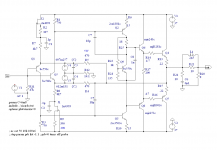
Without input filter 0 to 6 MHz and with input filter 0 to 600 kHz.
Probably better to filter it a bit down.
Loop Gain bandwidth 0 to 15 kHz with 80 dB, 70 dB at 20 kHz.
BR Damir
It was not possible to simulate correctly slew rate because of protection zeners, after removal all was as it should. I am not sure if zeners from LTspice library are OK.
Last edited:
Thanks for this Guru Zan.Ok. I've had a think, skip Dr Hurst, I can do this myself.
Post the ASC for #500 and I will demonstrate.
I grovel at your feet.
Attachments
Thanks...
What you have sent doesn't quite match #500.
C7 is connected to the Vbe multiplier.

Presumably this is an error and it is intended to match #500?
Best wishes
David
I've been playing with various compensation schemes in the dark cos I haven't got the right tools.What you have sent doesn't quite match #500.
C7 is connected to the Vbe multiplier.
Presumably this is an error and it is intended to match #500?
Both versions are valid and would benefit from a closer look using both
- the 'inner loop' probe between R13/15 and R4/5
AND
- the new 'main loop' probe which I'm hoping you'll show us.
I don't see much 'real' difference in THD between the 2 versions.
I also swapped from 'high gain' 2n5551/5401 to Lo Ccb 2sc3503/a1381 when I realised that the IPS/VAS interface did not benefit much from high gain VAS devices but would from Lo Ccb. But the difference is also small until you use the 'hand carved by virgins power rails' in #1431 cfa-topology-audio-amplifiers
Last edited:
Yes. Mea maxima culpaAre you sure?
It looks to me that one side is Miller compensated and one side is Output Inclusive.
I remember from dim & distant 'real life' that doing something yucky like this didn't really cause problems .. but its a symptom of fudging by the unwashed masses rather than correct design .. which is what Holy 'pure Cherry' deserves
I did it on a 1975 Hitachi style circuit with LTP input like Fig 7.14 of Cordell's book but simpler as is my wont.
________________________
Bob, if you are lurking, I think Q5 in that pic should be diode connected rather than Q6 in the current mirror.
________________________
Actually more like Self 4th ed Fig 4.21 where he pontificates on the evils of this circuit ignoring its good points. This is actually one of my favourite VFA topologies if 1pp zillion THD isn't essential.
I believe he has new rants about this in his new 6th ed. Anyone have a copy and can summarize these new evils for dis beach bum?
Wahab, what about YOUR designs?
Are the criteria in #101 what you strive for? What THD figures can you achieve with these restrictions?
As expected low frequencies distorsions are not a problem
it s once we get to 10KHz or so that the numbers are difficult
to improve , something like -90dB at 20kHZ is about what is
possible if stability under capacitive loading without LR network
is a consideration.
Damir, did you recieve my email or pm ??
The emails I sent were all returned to sender...
Manso, no I never received your email, could be that my email was full, try now.
BR Damir
Got a design and/or .ASC you can show us?As expected low frequencies distorsions are not a problem
it s once we get to 10KHz or so that the numbers are difficult
to improve , something like -90dB at 20kHZ is about what is
possible if stability under capacitive loading without LR network
is a consideration.
My Jurassic scribblings suggest its not possible but this was in the 80's with much cruder tools and devices were much worse.
-90dB is 0.003% THD which would have been considered SOA in dem days.
IMveryHO, you need to look at both the inner loop(s) AND Loop Gain for the whole amp. Like Bob, I believe (and have some limited 'real life' evidence of this,) each encompassing loop will also show problems in any inner loops.
Certainly need to look at both loops, indeed all loops.
Problems in inner loops will show in outer loops but can be less than obvious.
It may have no impact on the PM/GM at all.
Hence if you want a single PM/GM figure, you should use the Loop Gain for the whole amp
The desire for just one number is natural, but simplistic.
Some properties just need more complex metrics.
If you insist on a simple metric then the best is probably the minimum of all the loops.
The fact that the instability of an inner loop may not affect the outer loop GM/PM makes that a poor metric.
To put it other words, just because it is the outer loop does not mean that it is the dominant loop.
Best wishes
David
Last edited:
Yes. Mea maxima culpa
That's exactly why I said I wanted a ready to run circuit with no "little" alterations
But if you post #500 I can still demonstrate the Tian probe for that style of input.
Bob, if you are lurking, I think Q5 in that pic should be diode connected rather than Q6...
Well spotted.
Best wishes
David
Err.rh! We've been through all this before.Problems in inner loops will show in outer loops but can be less than obvious.
It may have no impact on the PM/GM at all.
......
The fact that the instability of an inner loop may not affect the outer loop GM/PM makes that a poor metric.
To put it other words, just because it is the outer loop does not mean that it is the dominant loop.
Anyone dig out a non-trivial or non-stupid case where an unstable 'inner loop' doesn't lead to an unstable 'outer loop'?
Both Bob & I asked this question and got no replies.
At the end of the day, the closed loop response is THE outermost loop. If it is OK, it matters little what is happening inside if you can't see any of it from outside the box.
That's why I prefer to exercise stability using wonky loads etc. .. just like I would in 'real life'.
All dis 'linear' stability sh*t is only cos we like to pretend to design in this 'real life' stability on wonky loads etc.
In da 21st century, the best SPICE world 'linear' stability metric is to simply close the loop and check for peaking and oscillation.
It would be nice to do this in 'real life' too and I hope Bob keeps his promise to tell us how to measure frequency response to 100MHz easily in his next edition.
But Loop Gain plots / Nyquist etc are useful if you need to improve stuff.
__________________
I'm still playing with my CFAs. It's pretty obvious the missing tool is some way of looking at Loop Gain for the whole amp, the 'outermost loop'.
I can get the 'inner loop' stable using Guru Zan's Tian probe at the output. But without some way of looking properly at the 'outer loop', I'm struggling in the dark.
Use the .ASC I just posted. It shouldn't matter what type of compensation is used.But if you post #500 I can still demonstrate the Tian probe for that style of input.
Only that your new Tian probe position for simple CFA inputs should show the Loop Gain for the 'outermost loop'.
Many thanks
Here is CFA amp with low FB of 32 dB and it’s flat up to 100 kHz. Distortion is going up, of course, and harmonics slop down monotony. Some people say that this should sound better then high feedback and lower distortion but with not so good harmonic distribution. The amp is very stable, with no output inductor and up to 70 nF at the output. With output inductor of 0.5 uH only(John Curl maximum allowed value) it is stable on all reasonable capacitances.
BR Damir
BR Damir
Attachments
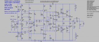
I would class that as as a high performance amplifier:
Distortion at least 2 orders of magnitude BELOW other signal chain element distortion levels (speakers, vinyl, room acoustics, ear etc)
Good slew rate performance
Monotonic distortion spectra
Good gain and phase margins
I have concerns about matching the OPS mosfets and C10/C16 impact on PSRR, and the TIS collector base resistors - but, I think overall this design has some solid benefits.
I would class that as as a high performance amplifier:
Distortion at least 2 orders of magnitude BELOW other signal chain element distortion levels (speakers, vinyl, room acoustics, ear etc)
Good slew rate performance
Monotonic distortion spectra
Good gain and phase margins
I have concerns about matching the OPS mosfets and C10/C16 impact on PSRR, and the TIS collector base resistors - but, I think overall this design has some solid benefits.
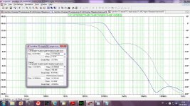
I don't think that the matching is going to be a problem, laterals from same batch are quite matched. C10/C16 could be removed they dont influence stability, but PSRR simulation shows no difference with or whitout them. PSRR is about 56 dB at 100 Hz and going down to 48 dB at 10 Hz. Good cap multipliers for IPS could better PSRR.
Regarding TIS local feedback resistors, I simulated whitout them and with differente resistors values. Without them lopp gain is 70 dB but distortion spectra is not so good. Value of 220 kohm gives 32 dB of feedback and much better distortion spectra and not so high distortion. Don't forget that this amp is very stable and 0.5 uH output inductor is more then enough if any is needed.
BR Damir
Ah yes thanks Bonsai for your opinion.
Last edited:
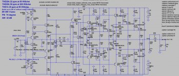
This is my final 200 W/8 ohm, 400 W/4 ohm CFA amp. It is not of extreme low distortion, but it is very stable, even to 200 nF load with no output inductor. It's no to simple I admit, but what the hack, simplicity is not my peace of cake.
BR Damir
BR Damir
Attachments
- Home
- Amplifiers
- Solid State
- 200W MOSFET CFA amp