This wont change the fact that there will be at most 66dB loop gain
around the output stage.
That you end with 40db global NFB and 26db local
NFB around the VAS/OS will still be 66dB , unless
you re counting thoses 26dB two fold , for the local
loop and another time for the global loop......
I don't count just simulate. Try to simulate it with your spice and then tell me what result you've got.
Why do you need the extra drivers..?? running the laterals off Q6 and Q8 should be entirely possible, or do you prefer the extra gain to get the numbers down..??
I simulated first with no aditional drivers and result were not good. Latfets high input capacitance is not good for relative high VAS output impedance and I choose the drivers with low Cob with much better result.
By the way drivers don't add any gain.
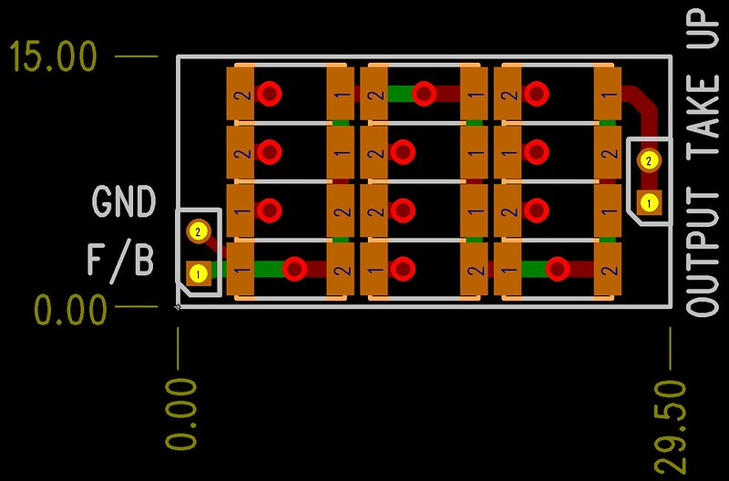
How would you attach it to the main PCB?
This is a double sided sub-board placement intended to be attached to the main board with pin headers. The resistor string consists of 24 pieces of 2512 resistors, including the shunt resistor, therefore the GND net is included in the connections.
Last edited:
I don't count just simulate. Try to simulate it with your spice and then tell me what result you've got.
I dont throw numbers without checking...
Anyway , try with a 33nF connected from output to ground ,
a sine will be enough.
Just for fun
R61 and R62 are incorrect value in your sim.
Just for fun I did this...
A bootstrapped driver version.
Benefits from reduced component count and not using the KSA/KSC transistors for drivers.
THD is slightly worse at 1Khz..
R61 and R62 are incorrect value in your sim.
Just for fun I did this...
A bootstrapped driver version.
Benefits from reduced component count and not using the KSA/KSC transistors for drivers.
THD is slightly worse at 1Khz..
Attachments
Damir, are you using EKV models for your output FETs?
Bob Cordell points out in his book that without EKV models, any THD sims of FET outputs are fairy tales.
I like FET outputs too but aren't using them for my Adventures in SPICEland because of this.
No I don't, I don't know that anyone in this forum use it. I don't have EKV models for those laterals, if someone have them I would like to sim with them. It is not supper low THD the goal here, and even the simulation I did shows direction of improvement.
I dont throw numbers without checking...
Anyway , try with a 33nF connected from output to ground ,
a sine will be enough.
You mean directly to the output without inductor? Why to do that?
You mean directly to the output without inductor? Why to do that?
I know the inductor is supposed to isolate the amp from capacitive loads but it's not a bad idea, IMO, to simulate these sort of loads. It's something I did with my CFA. Stability is the number one priority, no good having an amp if its unstable. If I remember correctly I got to 80nF in sims before oscillation took hold.
You mean directly to the output without inductor? Why to do that?
To check stability.
To check stability.
What is maximum practical(recomended) capacitive load, before inductor, with an amp should be stabil?
You see 100nF (with no resistive element) stated round here quite a bit. A very extreme load...
Yes but after inductor not connected directly to the output. This is used in the square wave test with coapacitive loading. If the amp should be stabil with such high capacitive load with no inductor then 10 to 15 dB gain margin recomended by some(I think Cordell recomendation it too) is not enough. To make my CFA amp stabil with 30 nF direct load I incresed GM from 13 dB to 23 dB, and of coarse that is paid with increase in distortion.
Wahab, I would like to know what you use too.What is maximum practical(recomended) capacitive load, before inductor, with an amp should be stabil?
")
I know of only 3 commercial amps which are unconditionally stable with all loads without an output inductor. None would be considered low THD today.
There are Golden Pinnae amps without output inductors but these are unstable on many real speakers. All dependent on their overload & thermal history too. No wonder they sound different and are picky about speakers.
Yes you've got it right Bonsai, this twist in TPC(connection to the output instead to the VAS collector) improve HF distortion a lot and with BJT's it did not work(for now).
Hi Damir
Have you looked at the inner loop around your OPS?
I checked your ASC from post #74 and found the OPS ULGF is just a bit more than 19 Mz.
That is extreme for an output and partly explains your excellent distortion results.
I am not surprised it didn't work with BJTs
Do you think this is realistically achievable?
Best wishes
David
Last edited:
Hi Damir
Have you looked at the inner loop around your OPS?
I checked your ASC from post #74 and found the OPS ULGF is just a bit more than 19 Mz.
That is extreme for an output and partly explains your excellent distortion results.
I am not surprised it didn't work with BJTs
Do you think this is realistically achievable?
Best wishes
David
I think it is, maybe needs some compensation adjustment but not much.
BR Damir
What is maximum practical(recomended) capacitive load, before inductor, with an amp should be stabil?
Good question for wich i have personaly no other answer
than a purely subjective one since it s based on preference.
Generaly i prefer designs that can stand several hundreds nF
with no other consequence that the usual ringing when using
a square signal for tests , relying too much on the output LR
seems to me a bad practice.
Of course in real world we ll hardly have to deal with pure
capacitive loads since a few meters of speaker cable are
already enough to provide some dumping if ever a filter
is too capacitive.
I know of only 3 commercial amps which are unconditionally stable with all loads without an output inductor. None would be considered low THD today.
THD being a notion that is more or less understandood
by any consumer it has become some kind of corner
stone when compairing amplifiers and as such it is
given more attention at the expense of stability
wich is not a selling feature , no one will be impressed
or will understand if you say that your product has
x db gain margin and y degrees phase margin but from
0.01% distorsion to 0.001% it is easy to conclude
that the latter is , well , ten times more accurate
than the former.....
What do you use for 'real world' testing?Good question for wich i have personaly no other answer than a purely subjective one since it s based on preference.
Generaly i prefer designs that can stand several hundreds nF with no other consequence that the usual ringing when using a square signal for tests , relying too much on the output LR seems to me a bad practice.
- Home
- Amplifiers
- Solid State
- 200W MOSFET CFA amp