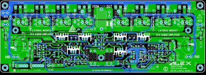
I think that the C12 and C15 will have to be a little bigger, the 16mm dia. is a little small. I did not find any of that size on Ebay, maybe someone could suggest a source. I have 19mm caps of that spec. but they will fit only if I change the layout, which is very easy and doable there is room to do it.
Also R9 should be of 1W, make a space for bigger resistor.
Also R9 should be of 1W, make a space for bigger resistor.
Always BOM neded when a PCB are layout and so will be not so many revisions.

Alex
Always BOM neded when a PCB are layout and so will be not so many revisions.
Alex
Yes Alex you are completely right, I am to slow (probably age).
As this amp has very similar input stage I gave a list of important data for Unique amp here http://www.diyaudio.com/forums/solid-state/253039-unique-cfa-120-230w-amp-5.html#post4105613 and there is R9 the feedback resistor with the same data. Sorry for confusion.
BR Damir
... Attached is the zip file with two last presented 200W LMOSFET amp and if you find the time to play with it...
Hi Damir
I had a closer look at your circuit, it was not quite what I expected.
I would say it is closer to ordinary TPC around the VAS, with an extra OIC component.
The OIC branch works very well to tweak the Two Pole VAS/Miller loop with some extra gain just where needed, very neat.
Better than a Two Pole OIC loop, which is what I understood you to mean, before I checked the circuit.
I think your compensation for this circuit is close to optimal, even theory predicts any improvements will be small, in practice probably smaller than model inaccuracies anyway.
I did try MIC but it does not seem to suit your CFA front end, not sure why, it performs well on my VFA test circuit.
In fact the best result I had was simply to increase the OIC capacitor a little.
Try 39p to 42pF, the stability looks a little better, distortion is essentially identical.
Very educational and so I will continue to experiment, but you don't have to worry I will make the compensation obsolete.
Best wishes
David
Last edited:
Hi Damir
I had a closer look at your circuit, it was not quite what I expected.
I would say it is closer to ordinary TPC around the VAS, with an extra OIC component.
The OIC branch works very well to tweak the Two Pole VAS/Miller loop with some extra gain just where needed, very neat.
Better than a Two Pole OIC loop, which is what I understood you to mean, before I checked the circuit.
I think your compensation for this circuit is close to optimal, even theory predicts any improvements will be small, in practice probably smaller than model inaccuracies anyway.
I did try MIC but it does not seem to suit your CFA front end, not sure why, it performs well on my VFA test circuit.
In fact the best result I had was simply to increase the OIC capacitor a little.
Try 39p to 42pF, the stability looks a little better, distortion is essentially identical.
Very educational and so I will continue to experiment, but you don't have to worry I will make the compensation obsolete.
Best wishes
David
Thanks David, I fell easier now, appreciate your effort.
Cheers Damir
David, have you notice that the ULGF ... increases with ... OIC cap value, contra intuitive to me?
It makes sense that the increased capacitor increases the ULGF.
What is a bit counter intuitive is that this increase can actually improve the stability, but the theory is clear even if it is unexpected.
The modification increases the peak of the phase improvement from the Bode step, and places the peak just at the ULGF.
Sometimes it is hard to have both the size and the position correct simultaneously, try to improve one aspect and the other becomes worse.
But here it looks very satisfactory.
What improvement in PM do you see?
(I messed up your circuit when I first experimented, want to check I have it fixed
)Best wishes
David
It makes sense that the increased capacitor increases the ULGF.
What is a bit counter intuitive is that this increase can actually improve the stability, but the theory is clear even if it is unexpected.
The modification increases the peak of the phase improvement from the Bode step, and places the peak just at the ULGF.
Sometimes it is hard to have both the size and the position correct simultaneously, try to improve one aspect and the other becomes worse.
But here it looks very satisfactory.
What improvement in PM do you see?
(I messed up your circuit when I first experimented, want to check I have it fixed
Best wishes
David
Wait a moment David, now you confused me. Increasing compensation cap does improve the stability and I expected that, but normally in the same time decrease the ULGF and LG at the HF. I see increase in the ULGF only with OIC. I did not analyze way, maybe I should.
Increasing OIC cap from 33p to 42p increased the ULGF from 3.82 MHz and PM from 78 degree to 3.97 MHz and 88 degree. Distortion change is not significant. It looks that OIC cap value is not so critical. I love OIC!
Cheers, Damir
ps. you can always reload .asc files
Last edited:
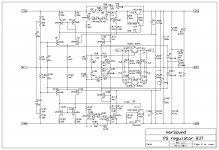
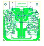
Damir, is there a PDF file of the regulator board to enable iron transfer method for diyers? Can the power transistors be 2SC5200/2SA1943 and the drivers TIP31/32/41/42? Thanks.
I am not sure about those transistors, not familiar with them, regarding Vce and Vcb you should chose B or C type but Ft is quite low.
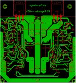
I will prepare a PDF files.
Damir
That you. 5200/1943 are the same as the MJLs shown in your schematic but with 150watt Pd. Yes the TIP transistors have a lower Ft than MJE1500x types, as well as lower gain, but does this matter in the regulator circuit? What is dissipation of the power transistors? Thanks again.
That you. 5200/1943 are the same as the MJLs shown in your schematic but with 150watt Pd. Yes the TIP transistors have a lower Ft than MJE1500x types, as well as lower gain, but does this matter in the regulator circuit? What is dissipation of the power transistors? Thanks again.
Oh sorry, I meant TIP type transistors, of course you can use 5200/1943.
You know they say an amp is good as its power supply, so I would stay out of TIP transistors, but you can try them. I use similar PS regulator, just with lower voltage, daily in my TT amp and I am very satisfied how it behaves and "sounds".
Damir, thanks for your quick response. I have a few more questions. You are so proficient in publishing circuits at a pace which most of us cannot keep with. So, which of your amps is the best sounding? Are there others out there which sound better and you are trying to match? Regarding the regulator, what is the maximum continuous current draw permissible and can it be used for a Class A amp with steady draw of 3.2Amps per rail? Minimum voltage drop and maximum dissipation? Thanks again.
Damir, thanks for your quick response. I have a few more questions. You are so proficient in publishing circuits at a pace which most of us cannot keep with. So, which of your amps is the best sounding? Are there others out there which sound better and you are trying to match? Regarding the regulator, what is the maximum continuous current draw permissible and can it be used for a Class A amp with steady draw of 3.2Amps per rail? Minimum voltage drop and maximum dissipation? Thanks again.
Sam, I have built some of my amps not all. I still did not build any of my CFAs, this is quite expensive hobby, I am retired and how much I would like to build more amps specially some of those CFA types I can't afford it. I hope someone soon will build some of my CFAs.
The best sounding of my built amps is ThermalTrak amp with TMC. I have designed some simpler "blameless" types too with TMC and variations, but TT amp was may effort to use all, known to me, improvements in a VFA, and I enjoy its sound very much.
You can use this PS regulator for Class A amp, but it was design specially for Class B amps.
Beware that this is +-65 V version, I think way to high for an A class amp.
I will post the PDF file, just need more time to check the layout as in this one I changed some transistors for higher voltage type, from CBE to EBC.
If you want more information go here http://www.diyaudio.com/forums/powe...ply-cap-multiplier-electronic-protection.html where I tried to explain the function.
Damir
Thanks Damir, for your effort and response. I have got all the answers I needed from the thread you pointed to. I want to use this for +-24V, 2.40 Amps and +-35V, 3.20 Amps. Is there an updated schematic? Thanks again.
Schematic is the same just have to change some resistors value. I need some time to simulate it.
Is there any interest in a SMALL group buy for this board? I have a quote for about $100 for 5 boards. I can get quotes for larger numbers of boards.I think that the C12 and C15 will have to be a little bigger, the 16mm dia. is a little small. I did not find any of that size on Ebay, maybe someone could suggest a source. I have 19mm caps of that spec. but they will fit only if I change the layout, which is very easy and doable there is room to do it.
Attachments
Is there any interest in a SMALL group buy for this board? I have a quote for about $100 for 5 boards. I can get quotes for larger numbers of boards.
Don't forget to make a space for bigger R9 22R resistor, it should be min 1W or better 2W.
- Home
- Amplifiers
- Solid State
- 200W MOSFET CFA amp