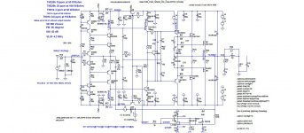
Damir, THD sims on MOSFET amps are fairytales without EKV models. IIRC, Cordell's book has details. Bob promises us EKV models when he gets a round tuit.I did some more simulation and came to this a bit simpler schematic. No need for individual OPS mosfet compensation, distortion is still very low, clipping is good, SR is 700 V/usec with no input filter and 200 V/usec with input filter.
")
Damir, THD sims on MOSFET amps are fairytales without EKV models. IIRC, Cordell's book has details. Bob promises us EKV models when he gets a round tuit.
Those are Cordell's models, not EKV, but still pretty good according to David and used in Toni's amp and simulated result was quite close to the real thing.
Cordell's models are good for stability but THD sims will be wonky.Those are Cordell's models, not EKV, but still pretty good according to David and used in Toni's amp and simulated result was quite close to the real thing.
Mr. Zan, can you confirm your experience with these Cordell models.
Cordell's models are good for stability but THD sims will be wonky.
Mr. Zan, can you confirm your experience with these Cordell models.
Toni played around with a VFET VAS and found the "MOS" model underestimated distortion by a factor of about 50.
That makes sense, the "MOS" model he used did not handle capacitance variation well.
So I recommended he try Cordell's VDMOS model.
This improves the capacitance variation model but still does not include sub-threshold conduction.
Somewhat to my surprise, this model predicted distortion fairly consistent with Toni's measurements.
So most of the distortion, in this case anyway, seemed to be from the capacitance variation, and sub-threshold conduction was minor.
I don't claim to be an expert on this, have studied the Spice models to help Toni.
I don't think I will bother with it much more, I use BJTs myself, and it was not well received when I tried to help in the "CFA rumble" thread.
Someone asked whether some MOS models were OK (they weren't).
Perhaps I was tactless but it was like I called their kid stupid
Best wishes
David
I do have a little more support for the use of the VDMOS model.
As you know, for a practical class B amp with reasonable bias the OPS is the main source of distortion.
So you can estimate the distortion fairly accurately just from the loop gain because that sets the reduction due to feedback, it doesn't depend too much on the details.
When I see claims for implausibly low distortion from simplistic amps I sometimes check to see where the mistake is, it's often from use of "MOS" models.
Recently both Damir and I noticed such a case. It was a nice, simple little amp but claimed 4 PPM!
When the "MOS" models were replaced with Bob's VDMOS models then the simulated distortion increased to about what you would expect for that circuit - about .012% @ 20 kHz.
That seems realistic and tends to confirm my idea that those models are reasonable.
It is also quite acceptable for an amp of that kind but the creator was not happy to receive this reality check.
He seems a decent bloke so I took the time to explain the models a bit, and that's when the complaints started, not from him I should add.
Best wishes
David
Last edited:
I do have a little more support for the use of the VDMOS model.
As you know, for a practical class B amp with reasonable bias the OPS is the main source of distortion.
So you can estimate the distortion fairly accurately just from the loop gain because that sets the reduction due to feedback, it doesn't depend too much on the details.
When I see claims for implausibly low distortion from simplistic amps I sometimes check to see where the mistake is, it's often from use of "MOS" models.
Recently both Damir and I noticed such a case. It was a nice, simple little amp but claimed 4 PPM!
When the "MOS" models were replaced with Bob's VDMOS models then the simulated distortion increased to about what you would expect for that circuit - about .012% @ 20 kHz.
That seems realistic and tends to confirm my idea that those models are reasonable.
It is also quite acceptable for an amp of that kind but the creator was not happy to receive this reality check.
He seems a decent bloke so I took the time to explain the models a bit, and that's when the complaints started, not from him I should add.
Best wishes
David
Yes David, I followed that, sometimes people take an offer of help as a personal attack.
BR Damir
Which thread is this Dave?Recently both Damir and I noticed such a case. It was a nice, simple little amp but claimed 4 PPM!
When the "MOS" models were replaced with Bob's VDMOS models then the simulated distortion increased to about what you would expect for that circuit - about .012% @ 20 kHz.
That seems realistic and tends to confirm my idea that those models are reasonable.
It is also quite acceptable for an amp of that kind but the creator was not happy to receive this reality check.
He seems a decent bloke so I took the time to explain the models a bit, and that's when the complaints started, not from him I should add.
Novel DC servo
I would like to get some comments on this way to implement DC servo. It is connecting via +- capacitance multipliers and do two works in the same time, power filtering and DC servo.
What I know it was not used before.
Damir
I would like to get some comments on this way to implement DC servo. It is connecting via +- capacitance multipliers and do two works in the same time, power filtering and DC servo.
What I know it was not used before.
Damir
Attachments
I would like to get some comments on this way to implement DC servo. It is connecting via +- capacitance multipliers and do two works in the same time, power filtering and DC servo.
What I know it was not used before.
Damir
Greetings Damir
Nice simple design.
How about trying EF triple but with mosfet outputs.
Greetings Damir
Nice simple design.
How about trying EF triple but with mosfet outputs.
Hi Manso,
Long time no hear. What do you mean by EF triple but mosfet output? Do you mean bjt predrivers and drivers and mosfet output?
What do you think of may DC servo connection?
Hi Manso,
Long time no hear. What do you mean by EF triple but mosfet output? Do you mean bjt predrivers and drivers and mosfet output?
What do you think of may DC servo connection?
Unfortunealy business side is taking up a lot of my time, I prefer the engineering side but it doesnt pay the bills.
Thats it, will provide better THD figures.
Interesting, Id like to take a closer look, asc file pls.
Last edited:
Unfortunealy business side is taking up a lot of my time, I prefer the engineering side but it doesnt pay the bills.
Thats it, will provide better THD figures.
Interesting, Id like to take a closer look, asc file pls.
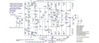
Asc, here.
Attachments
Hi damir, sorry I just have little time, very busy lately.
I have take a brief look at your DC servo.
your servo will have more than one pole, so there will be probably overshoot, do a transient analysis with the opinion "start dc external voltage at zero volts" and a long stop time like 60 seconds , and maximum time step of 1 second (I think this values will work ) . see the time it takes to the output reach a steady state. and please report back, I am curious.
I have test some DC servo similar to yours in the past with not so good success, unfortunately.
Ok, I have test your circuit, it took 3 minutes to settle to zero volts at output, but no overshoot, the circuit is to slow to be affected by audio signal ( that's a good thing ).
One thing that you may try to improve is the fact that for correct 120mV at amplifier output the servo opamp output was at 4volts.
now that I think about it... the DC servo similar to yours that I test was in a DAC current to voltage converter, the DAC have no capacitors at the output so a slow servo was not a good idea, but in a power amplifier it may work.
DC Servo --- Generally speaking, you do not want to create differential changes on the power supply -- or you need very high psrr if you do have DM conditions. A more sneeky affect is the altering of devices' C with supply changes....... something the models seem to be lacking in showing but will show up on real built circuits as increased distortion.
THx-RNMarsh
THx-RNMarsh
Last edited:
Ok, I have test your circuit, it took 3 minutes to settle to zero volts at output, but no overshoot, the circuit is to slow to be affected by audio signal ( that's a good thing ).
One thing that you may try to improve is the fact that for correct 120mV at amplifier output the servo opamp output was at 4volts.
now that I think about it... the DC servo similar to yours that I test was in a DAC current to voltage converter, the DAC have no capacitors at the output so a slow servo was not a good idea, but in a power amplifier it may work.
Thanks Sergio,
I am more concerned with 20 V pulse on the output at the power on, it must be the way I generate +- 15 V for the DC servo.
DC Servo --- Generally speaking, you do not want to create differential changes on the power supply -- or you need very high psrr if you do have DM conditions. A more sneeky affect is the altering of devices' C with supply changes....... something the models seem to be lacking in showing but will show up on real built circuits as increased distortion.
THx-RNMarsh
Difference changes provoked by the DC servo on the power supply are very small, only 76 mV in this particular case of simulation. I don't think that is possible to have less difference on real power supply between + and - voltage even without this DC servo.
BR Damir
Which one of the op amps are you using the LF411 or the LT1022?
LF411 is better suited to do DC servo job, but I don't have spice model for it and use LT1022 instead. An opamp with jfet input is good for DC servo.
- Home
- Amplifiers
- Solid State
- 200W MOSFET CFA amp