After some discussions in the LiteAmpThread I guess you would prefer a more constant loop gain and phase over the entire audio range.
Here a postfilter feedback version which would serve this design goal, however it will have much higher THD.
But I understood THD is not your concern, because the ClassD amp will only move the supply rails of the ClassA amp.
The attached version should be easy to mod from standard designs with IRS2092.
I have chosen low resistor values in the small signal area. From perspective of IRS2092 you could go for approx 3 times higher resistor values and 3 times smaller capacitances if your layout is good enough.
Thank you ChocoHolic,
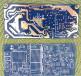
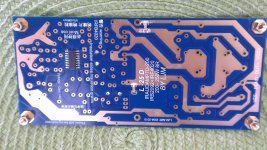
This is the PCB I bought, it's standard one on Ebay.
BR Damir
Attachments
The power amp I will use is modified 100W CFA and 200/400W Class D amp. This CFA is quite similar to my Class AB amp but the output MOSFETS are biased to Class A and power supply is only +-6V with middle point not connected to the ground but to the Class D amp output. Both amps should have the same gain.
The operating principle you propose has been used in a Technics amplifier.
This was examined in 1989 by Linsley-Hood who found a problem. In any event Technics dropped the subject amplifier from their product line up and moved to other approaches for their top models.
Linsley-Hood's analysis of the Technics example starts at page 11 in the link at http://www.keith-snook.info/wireless-world-magazine/Wireless-World-1989/Evolutionary Audio.pdf
Here a version which uses as much as possible identical components like
the IRAUD7.
Take care the component namings in my simulation are not identical to your board.
The files as shown are heading for constant loop gain and phase over
the entire audio range. For this the C2 (name acc. simulation) is shorted.
Optional you can use the C2 = 1nF without short and will get
growing loop gain below 10kHz.
Frequency adjustment in this set up can be done by small variations of C6 (name acc. simulation).
Attachments
Here a version which uses as much as possible identical components like
the IRAUD7.
Take care the component namings in my simulation are not identical to your board.
The files as shown are heading for constant loop gain and phase over
the entire audio range. For this the C2 (name acc. simulation) is shorted.
Optional you can use the C2 = 1nF without short and will get
growing loop gain below 10kHz.
Frequency adjustment in this set up can be done by small variations of C6 (name acc. simulation).
OK I have now something to think about.
Just as I am used to work with linear amps, does not the phase margin of 20 degree looks to small, or gain margin of 3.5 dB??
.. does not the phase margin of 20 degree looks to small, or gain margin of 3.5 dB??
...was thinking the same some years ago.
But this self oscilating system has a strong intrisic mechanism which stabilizes itself. While usually such low margins give headache with tolerances - here even larger component variations lead to a shift of other parameters in a compensating way.
I.e. when you increase R8, which lets you expect to lift the entire gain... - ...this beast will teach you different. I.e. increasing R8 will not just increase the gain of the OTA stage, it also leads to a larger carrier at the COMP pin which reduces the gain from comparator input to halfbridge output and finally loop gain changes just a little bit.
So whenever you change component values:
Let run the transient analysis of the switching model and check the size of the carrier at the COMP pin.
Then you can readjust the gain of E3 in the averaged model accordingly and of course also change the component value(s) in the averaged model.
Have a look to this with the simulation, it's an amazing system

Last edited:
...was thinking the same some years ago.
But this self oscilating system has a strong intrisic mechanism which stabilizes itself. While usually such low margins give headache with tolerances - here even larger component variations lead to a shift of other parameters in a compensating way.
I.e. when you increase R8, which lets you expect to lift the entire gain... - ...this beast will teach you different. I.e. increasing R8 will not just increase the gain of the OTA stage, it also leads to a larger carrier at the COMP pin which reduces the gain from comparator input to halfbridge output and finally loop gain changes just a little bit.
So whenever you change component values:
Let run the transient analysis of the switching model and check the size of the carrier at the COMP pin.
Then you can readjust the gain of E3 in the averaged model accordingly and of course also change the component value(s) in the averaged model.
Have a look to this with the simulation, it's an amazing system
I noticed that you use 12V for IRS2092 VCC, and somewhere in Lite thread it was said that the chip get to hot if VCC was set to 15V.
...think this was in another thread about hints for implementations with IRS2092 and was mostly linked heavy MosFets like the IRFB4227.I noticed that you use 12V for IRS2092 VCC, and somewhere in Lite thread it was said that the chip get to hot if VCC was set to 15V.
The gate charging losses grow with the square of the VCC and there is no need of more than 11...12V. Also they grow proportional with fs.
In case of your board, I would leave it as it is. Changing VCC usually also calls for double checking dead time adjustment....
Here a version which uses as much as possible identical components like
the IRAUD7.
Take care the component namings in my simulation are not identical to your board.
The files as shown are heading for constant loop gain and phase over
the entire audio range. For this the C2 (name acc. simulation) is shorted.
Optional you can use the C2 = 1nF without short and will get
growing loop gain below 10kHz.
Frequency adjustment in this set up can be done by small variations of C6 (name acc. simulation).
I was quite busy lately around house, no to much time for audio.
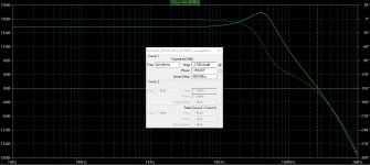
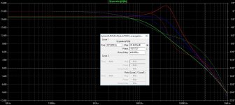
Before to completely assemble the PCB I did the loop gain simulation.
Here is my tray with the loop gain. I get best result removing C6 and C7. The gain is set to around 28 dB as I will use it together with my Class A of the similar gain.
I am not sure yet with this Class D simulation and I would like you opinion.
Damir
Attachments
Finally ")
It took pretty some time until someone started to ask these questions.
True. C7 & C6 are doing no good in terms of transfer function.
Unfortunately I still needed them in real life.
At least 1nF from COMP to GND is needed according data sheet.
..and yes, the data sheet is right. Without this cap the OTA tends to
fall into a MHz oszillation.
Furtheron please note that without this cap my simple model will anticipate an OTA with unlimited speed and will not properly reflect the real IRS2092. Especially when you remove C6 & C7 then the simulation will strongly deviate from real IRS2092.
The cap from COMP to OTA input is one of the 'lower impact solutions' to control the switching frequency.
Which switching frequency do you theoretically get from your set of values? Must be pretty high, I guess.
Finally
It took pretty some time until someone started to ask these questions.
True. C7 & C6 are doing no good in terms of transfer function.
Unfortunately I still needed them in real life.
At least 1nF from COMP to GND is needed according data sheet.
..and yes, the data sheet is right. Without this cap the OTA tends to
fall into a MHz oszillation.
Furtheron please note that without this cap my simple model will anticipate an OTA with unlimited speed and will not properly reflect the real IRS2092. Especially when you remove C6 & C7 then the simulation will strongly deviate from real IRS2092.
The cap from COMP to OTA input is one of the 'lower impact solutions' to control the switching frequency.
Which switching frequency do you theoretically get from your set of values? Must be pretty high, I guess.
Thanks you for explanations.
I get about 500 kHz, a bit to high, isn't it?
...I see you also massively increased R8, which lowers fs...
500kHz is not generally impossible. With the intended choke, MosFets and dead time this is more or less at the limit which still allows reasonable ZVS during idle.
But heat of the IRS2092 would need to be double checked.
And at high power the intended power stage will sweat already in a way which reduces reliability.
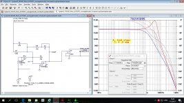
However I see that you did not readjust E3 according to the reduced size of the carrier signal at the COMP pin.
Attached the sim with readjusted E3.
==> Some more db loop gain. ==> Less margin.
Nevertheless - if the IRS2092 would have an ideal OTA your adjustment would be attractive.
With a real IRS2092 your proposal will suffer from instable OTA (unpredictably changing between nice operation and faulty MHz oszillations), and also fs and phase margin will be less, because without any external cap the internal pole(s) of the real OTA, which are not modeled in my sim, will become relevant.
500kHz is not generally impossible. With the intended choke, MosFets and dead time this is more or less at the limit which still allows reasonable ZVS during idle.
But heat of the IRS2092 would need to be double checked.
And at high power the intended power stage will sweat already in a way which reduces reliability.
However I see that you did not readjust E3 according to the reduced size of the carrier signal at the COMP pin.
Attached the sim with readjusted E3.
==> Some more db loop gain. ==> Less margin.
Nevertheless - if the IRS2092 would have an ideal OTA your adjustment would be attractive.
With a real IRS2092 your proposal will suffer from instable OTA (unpredictably changing between nice operation and faulty MHz oszillations), and also fs and phase margin will be less, because without any external cap the internal pole(s) of the real OTA, which are not modeled in my sim, will become relevant.
Attachments
Last edited:
...I see you also massively increased R8, which lowers fs...
500kHz is not generally impossible. With the intended choke, MosFets and dead time this is more or less at the limit which still allows reasonable ZVS during idle.
But heat of the IRS2092 would need to be double checked.
And at high power the intended power stage will sweat already in a way which reduces reliability.
However I see that you did not readjust E3 according to the reduced size of the carrier signal at the COMP pin.
Attached the sim with readjusted E3.
==> Some more db loop gain. ==> Less margin.
Nevertheless - if the IRS2092 would have an ideal OTA your adjustment would be attractive.
With a real IRS2092 your proposal will suffer from instable OTA (unpredictably changing between nice operation and faulty MHz oszillations), and also fs and phase margin will be less, because without any external cap the internal pole(s) of the real OTA, which are not modeled in my sim, will become relevant.
In your previous loop gain simulation you used 18k for R8, and I actually decreased it to 15k.
Just to summarize:
C7 is needed
C6 10 pF is OK but could be stable without it? simulation shows increased phase margin without
..sorry for confusion, somehow I had memorized it different.In your previous loop gain simulation you used 18k for R8, and I actually decreased it to 15k.

Yes, I am using C6 not for stability.C6 10 pF is OK but could be stable without it? simulation shows increased phase margin without
Actually it worsens stability of the global loop - fully agree to your findings.
In most versions I am using it to control fs.
In the 40V version it was additionally part of the fine tuning process of the shape of the carrier in order to get lowest THD.
IMHO using self oscillating tracking buck converters (Class-TD) at both rails to which collectors of output devices are attached is much better solution if someone wants to increase the efficiency of Class-A.
Could you suggest ready made self oscillating tracking buck converter and where to buy?
BR Damir
Damir, I don't think it's readily available anywhere.
Thanks, but now I have to start to learn about self oscillating tracking buck converters, and I'm to old for that. I will stick to Class D amps (possible to buy and adapt) as tracking power supply.
BR Damir
I would be interested in your approach... and I already have a pair of Crown I-Tech 5000 power amps which might be pressed into use with your Class A.
??
-Richard
Hi Richard,
As Class I amp is a kind of Class D amp (http://www.diyaudio.com/forums/class-d/87105-class-d-vs-class-i-balanced-current-amplifier.html) probably is possible to use it as variable part of the Class A amp power supply, but both have to have equal gain. Class A amp has its own high voltage low power supply and low voltage high high current supply.
As now is summer and I have to do much house maintaining, I don’t think I will have much progress before September.
BR Damir
- Home
- Amplifiers
- Solid State
- 200W Class A amp with high efficency