loop area rules.
That is what leads to the rule of:
close coupled pair for the signal wires.
You must identify the signal flow route and you as layout technician must ensure that the return route follows the flow route as closely as possible.
You must do that for every signal pair.
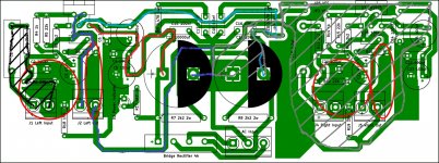
Thank you for your input. Base on my layout, could you tell me which components shall I ground and after grounding them, the trace go back to PSU?
Jeez this grounding thing is like a puzzle maze lol
How about now?

Wrong! Left Input Ground, C2,C3 and R2 - they should be together grounded (1 point)! And keep away output trace from input trace .
Wrong! Left Input Ground, C2,C3 and R2 - they should be together grounded (1 point)! And keep away output trace from input trace .
Thanks for your comment. It has been rectified prior to your comment and I put a 15R HBR according to http://hifisonix.com/wordpress/wp-c...re-up-a-Power-Amplifier_Updated-Autosaved.pdf

Forget about the ground word.Thank you for your input. Base on my layout, could you tell me which components shall I ground and after grounding them, the trace go back to PSU?
Sort out the signal pairs first.
Forget about the ground word.
Sort out the signal pairs first.
For my left input C2, C3 and R2 will be grounded with signal ground?
Left output R6 will be grounded with output ground?
For my right input C20, C21 and R12 will be grounded with signal ground?
Right output R16 will be grounded with output ground?
No.
Using the ground word is what is leading to the confusion.
At the input you have TWO wires bringing in the signal.
Those two wires are your signal pair.
For low loop area and low interference, these must be close coupled all along the route.
That is the priority that I mentioned in post40.
Make the LOOP AREA of the signal pair as small as you can manage.
Now repeat that process for EVERY signal pair in the amplifier.
After you have done that look at your schematic and compare to what you have as a layout proposal. If there are any missing links, eg voltage reference from input to output, then add in that missing voltage reference link. But add it in, in such a way that it can achieve it's purpose: to give an accurate voltage reference and not be interference contaminated by currents flowing along traces/wires.
Last edited:
Yes, but try using the word "return" instead, it may reduce confusion")
Duly noted sir.
@AndrewT: Are those encircled in red are the loop areas?

Last edited:
Have a look at page 6 on the much quoted link. Any circuit creates a loop, the area is the physical area within that loop, if it is large it is like a loop aerial and can both receive and transmit interference. That is why the area must be kept small by, in our case, keeping the flow and return as close as possible. In signal wires, coax or twisted pair is used to achieve this.
Have a look at page 6 on the much quoted link. Any circuit creates a loop, the area is the physical area within that loop, if it is large it is like a loop aerial and can both receive and transmit interference. That is why the area must be kept small by, in our case, keeping the flow and return as close as possible. In signal wires, coax or twisted pair is used to achieve this.
In my case, the entire length of the PCB is the loop area. But what about my signal returns, is it small enough? By the way, I added HBR. Have I connected it properly?
By the way, I added HBR. Have I connected it properly?
Yes, bare in mind it is to deal with the specific potential problem of a cross channel ground loop which can happen when you have more than one amplifier connected to a single power supply and was alluded to earlier. It's function is explained here page 4 onwards http://www.updatemydynaco.com/documents/GroundingProblemsRev1p4.pdf
Thanks Scott, I will try to read it later to better understand its function.
Hi Mark. Thanks to your illustration.
Does this loop will cause a significant noise?
Is it just best to have a separate board for the PSU to minimize loops?
Here are a few loops:
Input left (black).
There is a current from C12 to C26 and a return current from C26 back to C12 (grey).
Hi Mark. Thanks to your illustration.
Does this loop will cause a significant noise?
Is it just best to have a separate board for the PSU to minimize loops?
at this very early stage in your learning of PCB layout, you will find it a lot simpler to lay out one channel without an integrated PSU.
I said that back in post23 but you did not appear to attach any importance to my suggestion.
I said that back in post23 but you did not appear to attach any importance to my suggestion.
Once you have succesfully laid out (and built/tested) one channel and see what is required, then you can try to add on a PSU while still minimising the loop areas.You will find it much simpler doing a mono PCB with a separate PSU.
Last edited:
Hello guys. I'm back!
Three weeks ago I started this thread and I thank you all for helping me answering my queries. Despite all advises, I proceeded to etch my layout. It turns out to be a good build, no hum at all although I can hear some pops during On and Off. But I think this chip lacks a punch on the bass, other than that its pretty awesome. By the way, I am using 5A 24-0-24 PSU. Please watch the video and tell me your opinion about it. https://youtu.be/_ihINqhTt7Y


Three weeks ago I started this thread and I thank you all for helping me answering my queries. Despite all advises, I proceeded to etch my layout. It turns out to be a good build, no hum at all although I can hear some pops during On and Off. But I think this chip lacks a punch on the bass, other than that its pretty awesome
. By the way, I am using 5A 24-0-24 PSU. Please watch the video and tell me your opinion about it. https://youtu.be/_ihINqhTt7Y
Last edited:
Dual 24Vac for an LM1875 !
That seems very high.
What DC voltage have you got and what is your mains AC voltage?
Hi Andrew.
Our mains voltage is 220V after rectification, its giving 30V. I understand that the chip can handle 60V before it can be damaged. I've been testing it for a week now at full volume, infact it has been my companion when I was doing a paint job in our rooms
.- Status
- This old topic is closed. If you want to reopen this topic, contact a moderator using the "Report Post" button.
- Home
- Amplifiers
- Power Supplies
- 2 Separate Transformers