The measurements appear to me like you did not cut out room reflections.
The 18W will measure much flatter than this (the tweeter probably also), so you may be compensating things that are not actually part of the driver's behaviours. I built a similar speaker (contains FA123 and 18W/8531 woofers), so I can show you a measurement of the 8531G without any crossover. The measurement is with the woofer in a 230mm wide vented enclosure (tuning frequency is around 29 Hz, which is a bit low).
I recommend reading this for a start:
Loudspeaker measurements
Also, this is very helpful and is not applicable only to ARTA but to all loudspeaker measurements in small rooms without professional treatment:
http://www.artalabs.hr/AppNotes/AP4_FreeField-Rev03eng.pdf
In essence, you measure high and low frequency content for each driver separately and merge them afterwards. Low frequency content is measured in the near field, while high frequency components can be measured from a distance. Since the near field measurement does not show the influence of the baffle (and baffle step), you need to compensate for this fact. All the details are in the document.
Attachments
Last edited:
Hello Elagil!
You are right, i didn't cut out any room reflections. I am not sure how to do that in HFD..
I did read the first link you are linking to. More than once. However, when I measure from 1m distance I cant see anything from my impulse response - it just keeps swinging up and down (will post some images when i get home!). So i have no idea what size windows to make. I am completely new to all this measurement stuff so any inputs are much appreciated! I didn't read the second one, will do that!
However if i measure near field of both drivers without crossover then they look almost 100% identical to the ScanSpeak datasheets. The tweeter is dead flat way below crossover and the woofer looks like what you posted. I am sure that these old speaker cabinets are horrible when it comes to diffraction and such, so that probably does mess up the tweeter a bit when moving further away.
The measurement you show here is that near field, 1m or a combination?
Is it gated, smoothed and so on?
Looks like a text book example :O
Your drawings look very nice ! Still I suggest you try to play a little around with facets around the tweeter. If you have some cardboard it will take you 2-3 hours to test what is best.
I may be that the facet on top of the tweeter actually is not doing it any good - Or any harm for that matter. Instead you could make the facets less close to the frontplate of the tweeter. For an example of what I am thinking about look at Troels Gravesens ScanSpeak MUN17-3W (and neglegt the facet on the top) Anyway I think a placement of the tweeter quite close to the top of the baffle is a good starting point.
You are on the right track!
btw: How about the bracings - Have you thought about how to do them? - My opinion is more is always better. And go for a bracing matrix like.
For now i actually copied TG's Illumina-66 baffle. The MUN17 baffle is huge! I am building a small speaker here xD
I could of course try the cardboard now with my current cabinet maybe.. If the ideal cabinet shape is a sphere, then the facets should ideally start close to the front plate i guess?
I did, I can show a picture of that later too. I do have roughly 50% more bracing than the Illumina-66. I a pretty confident that this cabinet will be very solid!
Haha, maybe the freedom to make the baffle like that is limited. Still I think you should play a little. It may be that the smallest possible baffle is not the best one.
I would use a jigsaw to make a hole in some wood. Then secure the tweeter with screws. Point is - Make sure it is fastened. Dont fasten it with tape or something. From here use som thick cardboard. It often fits almost perfectly with the thickness as the frontplace. Just make sure it is leveled. You can use some "painting tape" to make a nice flat transition from the cardboard to the tweeter. Ready for experiments
Cool!
I think it is impossible with HFD, but you can just use REW.You are right, i didn't cut out any room reflections. I am not sure how to do that in HFD..
I was using around 2.5 ms window length for a measurement from 1 m. The whole impulse response is rather large. Try adjusting the scaling of the time axis.I did read the first link you are linking to. More than once. However, when I measure from 1m distance I cant see anything from my impulse response - it just keeps swinging up and down (will post some images when i get home!).
It is a combination of a 1 m measurement (gated 2.5ms) and near field, merged at around 500 Hz. I also generated a baffle diffraction compensation response with VituixCad, so that the near field response is actually similar to far field behaviour. The tutorial on how to generate this is in my second link. REW allows you to:The measurement you show here is that near field, 1m or a combination?
- Do far field measurements
- Do near field measurements
- Perform multiplication of signals (near field response and baffle step compensation)
- Perform merging of signals with automatic phase and amplitude adjustments
Measuring the tweeter in near field will not show baffle diffraction, as you say, which is not what you want. A gated measurement should work fine.
In general, I recommend using REW for taking your measurements and VituixCad for simulating the crossover. VituixCad supports the filters that your Hypex module provides. You can also simulate baffle diffraction for the tweeter. As stated, the diffraction effects will become negligible off axis quickly.
In VituixCad, you can also very easily merge near and far field measurements, as well as include baffle step compensation. It is a very capable application! If you need help, I can show you some screenshots.
That is probably a safe choice. You could also offset the tweeter (simulate in "The Edge" or VituixCad).For now i actually copied TG's Illumina-66 baffle.
Hey Danner,
Nice to see you back at it. In terms of measurement, I find REW quite simple to use as long as you get it set up correctly. Pretty simple too to build a little impedance measuring jig once you get the parts. I haven't read the measuring links provided so far, but Jeff Bagby spells everything out very clearly in these 2 links:
How to Achieve Accurate In-RoomQuasi-Anechoic Free-Field Frequency Response Measurements Down to 10 Hz
How to find the relative acoustic offsets
The acoustic offset paper is geared towards the Passive Crossover Designer program, but is actually even easier to do in XSim since there are no x, y and z coordinates to worry about. Merging of nearfield and farfield is also done by Jeff's Response Blender spreadsheet.
Those are what I use and can recommend but I have also heard some good things about VituixCad which does all of those things too.
As I mentioned before, none of the diffraction programs will do a completely accurate representation of your type of chamfered baffle so I'm with Rokytheman in terms of measuring with quick cardboard mockups if you want to get the flattest response out of your tweeter. But go back to my older post with the diffraction sims to get a general idea of what you will be dealing with - ie there is no need to offset the tweeter in the design you are implementing.
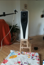
Okay, so yesterday i tried to redo everything based on what i learned from Saturday and your inputs. I bought a microphone stand. I put the speaker as far away from walls as i could and raised it so the tweeter was roughly 120 cm from floor and sealing. I was measuring from 1 m distance at a height right between the woofer and tweeter.
Attachments
This time i only used REW. I realized that there is some kind of issue with importing REW measurements to HFD - The simulated curve in HFD does not match the measured curve (around the crossover - some timing issue I guess) and as you say you can only do smoothing in HFD, you cannot do gating.
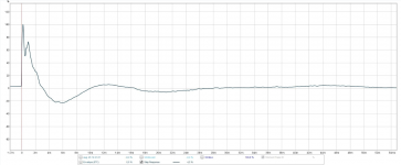
Elagil, i have a question. You gate at 2,5 ms. i guess you do this to eliminate all room reflections based on your setup? I calculated that i would receive reflections from 5 ms roughly. But when i look at near field impulse response of my woofer then it looks like i will be cutting away some of the signal. Does this impulse response (first image) not mean that i would need to stay above 30ms when gating? Or am I misunderstanding something?
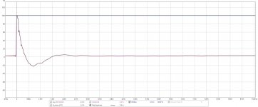
(I also attached the near field Tweeter impulse response (second image) as well. The woofer impulse from 1 m looks strange, or is it normal? - third image)
Elagil, i have a question. You gate at 2,5 ms. i guess you do this to eliminate all room reflections based on your setup? I calculated that i would receive reflections from 5 ms roughly. But when i look at near field impulse response of my woofer then it looks like i will be cutting away some of the signal. Does this impulse response (first image) not mean that i would need to stay above 30ms when gating? Or am I misunderstanding something?
(I also attached the near field Tweeter impulse response (second image) as well. The woofer impulse from 1 m looks strange, or is it normal? - third image)
Attachments
Last edited:
Elagil, it sounds like VituxCad in combination with REW is a must-master in this field, at least for crossover simulation and graph magic..
So I guess I will have to try and learn VituxCad. So i will definitely have questions! but maybe i should try to look at it first xD
But thank you so far!
jReave, Glad to see you are still following along! I certainly also like REW by now! Thanks for the reading, will give it a look!
Rocky and jReave, I copied TG's baffle to avoid doing these cardboard simulations. But now that you said it so many times and i start to get caught in this i may have to do it anyway.. Not sure how to go at it though. Rocky you said something like this right:?
* Cut a small piece of wood a little larger than the tweeter faceplate
* Mount the tweeter on top - not countersunk
* Cut cardboard to fit around it that can then be shaped to my shape
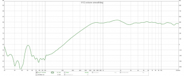
I am surprised how "flat" the tweeter measures in this cabinet though, I thought this baffle would be horrible! or is this measurement horrible? (first image is raw tweeter measurement at 1m with 4ms gating and 1/12 smoothing. Second is raw woofer near field measurement)
So I guess I will have to try and learn VituxCad. So i will definitely have questions! but maybe i should try to look at it first xD
But thank you so far!
jReave, Glad to see you are still following along! I certainly also like REW by now! Thanks for the reading, will give it a look!
Rocky and jReave, I copied TG's baffle to avoid doing these cardboard simulations. But now that you said it so many times and i start to get caught in this i may have to do it anyway.. Not sure how to go at it though. Rocky you said something like this right:?
* Cut a small piece of wood a little larger than the tweeter faceplate
* Mount the tweeter on top - not countersunk
* Cut cardboard to fit around it that can then be shaped to my shape
I am surprised how "flat" the tweeter measures in this cabinet though, I thought this baffle would be horrible! or is this measurement horrible?
(first image is raw tweeter measurement at 1m with 4ms gating and 1/12 smoothing. Second is raw woofer near field measurement)Attachments
Last edited:
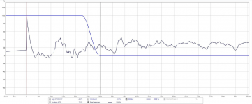
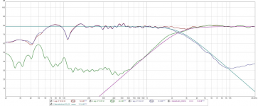
But well so far this was the result i got (First image is 30ms gating second is 5ms gating. Both are 1/12 smoothing). The filtering is only a high shelf -5.5dB at 550 Hz on the woofer to compensate for baffel step loss. And a LR24 at 2500 Hz on both drivers. On the first image all curves are shown, including the theoretical slopes of the LR24 filter.
As rocky pointed out there seem to bee something not right at 2000-4000 Hz, maybe phase issue? I did delay the tweeter 50mu s to compensate for the 20 mm-ish difference in acoustic center. It helped, it raised it from a 7 dB dip to 5 dB.
But I didn't have time to do more yesterday, and it did already sound pretty good and look slightly better than the old analog filter (it didn't compensate for the bafflestep loss). But will try to reverse the phase on on of them next time I have some time
Attachments
Last edited:
You do not need gating for the near field measurement, since the direct path is so much louder than any reflections. Also, gating limits the lowest frequency you can measure, so it does not make sense to do a gated near field measurement.
The woofer impulse response does indeed look strange. I will attach my woofer impulse response later, for comparing. You will see in the impulse response, when the first reflection arrives (as a secondary peak).
The woofer impulse response does indeed look strange. I will attach my woofer impulse response later, for comparing. You will see in the impulse response, when the first reflection arrives (as a secondary peak).
Looks like the impulse shown could be woofer and mid playing simultaneuosly with xo, same polarity.
Not so good timing is obviously causing the combined spl response to drop at xo. Change tweeter delay gradually and measure in series to find out which way the delay should be moved (less/more).
Not so good timing is obviously causing the combined spl response to drop at xo. Change tweeter delay gradually and measure in series to find out which way the delay should be moved (less/more).
Last edited:
Elagil, I know that gating isn't used for near field measurements. What I mean is that I thought the near field measurement showed the "True" impulse response of the woofer - since i obviously have an issue with the one from 1 m distance. And I thought I would ruin the measurements if i gated shorter than the impulse response of the driver, but that's not how it works?
The only thing that happens as the gating window goes shorter is that the lowest frequency you can count on is raised?
Just to make sure you have seen it. My near field impulse of the woofer looks correct (I think) but it is just the one at 1 m that looks wired.
Juhazi, The wired impulse measurement was done with only the 18W woofer connected in my old ported cabinets. It was measured from 1m distance.
Do you think it is just delay or should I flip the phase of one of the drivers?
Ok then it is driver and port signal - port is delayed by nature!
When setting delay this way, between two drivers, start with values at zero, measure with "right" and "reversed" polarity. Check spl response and step response of both measurements, identify which peak is which driver. Usually the higher playing driver needs some delay - add eg. 0,2ms delay and measure again, look for changes in spl and step response. etc. etc.
Another way to get idea of delay needed is to measure vertically off-axis (eg. 30¤) and compare that to on-axis responses (then physical offset is changed)
These tricks work only for symmetric LR or elliptical xos, that should sum well. LR2 has step peaks in opposite directions, LR4 in same direction and following each other.
W/M is easier to set than M/T because of longer wavelength/phase cycle, easier to get hold on this way. M/T might have phase mismatch for more than one cycle!
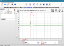
No, I don't think so. I also measure my 8531G00 from 1 m distance in a ported enclosure! Here is the impulse response in my case. Can you just repeat the measurement? Maybe there was some noise in the house or something else. You could also try averaging.
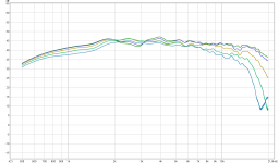
With regard to your baffle, it is not so horrible, really. Diffraction effects will also disappear off axis. Try to simulate it with VituixCad or the edge!
I built a similar geometry by accident, and I get a 5dB dip at 2.8 kHz (see attached, tweeter measurements under different angles) that completely vanishes from 30° onwards. Your tweeter behaves basically the same on your baffle!
Edit: I just noticed, you show the step response, which is not the same as the impulse response. Check the screenshot for reference.
Attachments
Last edited:
So I guess I will have to try and learn VituxCad.
What's nice about VituixCad is that it can pretty much take care of all your simulation needs from start to finish, not just do the xo sims. But if you want just a nice straight forward xo program, XSim is very good as well.
I copied TG's baffle to avoid doing these cardboard simulations. But now that you said it so many times and i start to get caught in this i may have to do it anyway.. Not sure how to go at it though. Rocky you said something like this right:?
* Cut a small piece of wood a little larger than the tweeter faceplate
* Mount the tweeter on top - not countersunk
* Cut cardboard to fit around it that can then be shaped to my shape
I forgot that you were going to model the chamfers after Troels' design, and that I was the one who suggested it.
 I expect that will be good enough especially when you are getting such a flat response in your current chamferless cabinet. Theoretically at least, even if it doesn't smooth out the FR that much more, adding the chamfers should improve sound quality in terms of imaging, as you are getting rid of or at least mitigating the sharp edges as secondary and delayed sound sources. For me, doing the cardboard modeling might depend on how anal I'm feeling or whether or not I like the aesthetics of Troels' chamfers vs something a little different. Or perhaps if I wanted to do it for the learning experience.
Rocky's method sounds good. You could also countersink the tweeter on a narrow piece of wood and then attach the cardboard as extensions off the sides. Either way, mock something up and through trial and error, I'm sure you'll get the hang of it.
Elagil sir, you are sharp! That explains everything xD Then i even see my reflections at around 4-5 ms! Thankyou
Then what dou you use the step response for?..
Aaah so that dip may actually be a diffraction effect!? I will try to measure off angle to see if it also disapears for me!
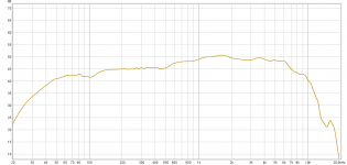
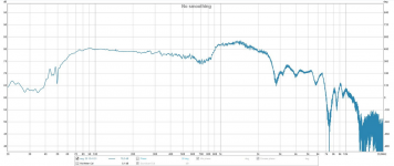
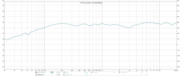
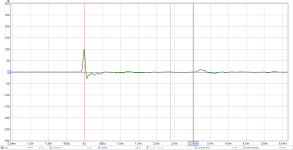
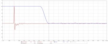
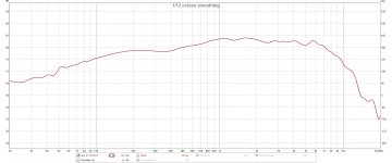
I attached my actual IMPULSE response of my woofer from 1m (first image) and its frequency response gated at 3,5ms and 1/12 smothing (second image). Does this look more normal then?
jReave, yes you did suggest it I might try it for the learning experience, but I have other things i have to test first! And i do like the look of this design very much!
VituxCad is the next program to learn it seems
Then what dou you use the step response for?..
Aaah so that dip may actually be a diffraction effect!? I will try to measure off angle to see if it also disapears for me!
I attached my actual IMPULSE response of my woofer from 1m (first image) and its frequency response gated at 3,5ms and 1/12 smothing (second image). Does this look more normal then?
jReave, yes you did suggest it
I might try it for the learning experience, but I have other things i have to test first! And i do like the look of this design very much!VituxCad is the next program to learn it seems
Attachments
- Status
- This old topic is closed. If you want to reopen this topic, contact a moderator using the "Report Post" button.
- Home
- Loudspeakers
- Multi-Way
- 18W, 12M and R3004 active 3-Way