It doesn't look like the compliance curve will be an issue for the spider. With such a small Xmax, it wasn't likely to have been an issue anyway.
There have been a few design changes so far:
- One of them is that I'll be going back to a single layer aluminum cone for ease of fabrication. Instead of spinning it like I originally thought, I'll just be rolling it as I would've done for the sandwich. The reason why the sandwich doesn't seem necessary anymore is because I looked at the response curve for the Dayton RSS460-HO, and it doesn't have any resonances until about 1 kHz. This is an 18" driver with a shallower cone, so if I make a deeper cone with roughly the same wall thickness, I should be able to raise the frequency of the first mode even higher. If I can't make it so that the first peak becomes a non-issue (e.g. after DSP), I'll epoxy on 12 reinforcing ribs, equiradially-spaced around the back side of the cone. These ribs will be approx 10 mm wide by 200 mm long x 1/4" thick balsa wood, with thin aluminum sheet laminated to both sides for high rigidity with fairly low mass.
- The basket is no longer made out of extruded T-slot. Again, the change was made for ease of assembly, as the centers and lengths of the attachments would have required "tweaking" in order to get all the parts aligned. The basket is now made from aluminum rods mounted on a very thick, high-rigidity laminated MDF plate. All alignment (centers and offsets) would be handled by CNC-milled holes and shoulder screws.
- Another change that's LIKELY to happen is that instead of using the motor backplate to connect to the basket, I'll use the motor top plate instead. The system becomes slightly more complex this way (probably) but the benefit is that the cone assembly can be fully assembled with good access, before the motor system is installed. This allows for greater flexibility in how the voice coil/voice coil former are made and attached.
- One benefit of using the metal spider is that it serves as a fairly safe excursion limiter, given that the spider will hit the top plate at Xmech. Luckily, it should be fairly resistant to this type of damage. However, at the time being, there is no such Xmech limiter for excursion in the opposite direction. Therefore, I'll be adding some plastic shoulder screws that will screw into the top of the top plate. The screws will be located such that the spider would whack the underside of the screw heads on over-excursion. It's just a simple drilling/tapping operation on the top plate, so I'll add 4 screws for symmetry.
One problem I was having with trying to actually make a copper sleeve for the center pole is that no matter how you size the center pole, the sleeve is going to need machining. However, machining a large-diameter thin-wall sleeve is rather tricky. Here's how I think I'm going to do it:
1) Procure a piece of copper tubing of oversize dimension (e.g. 4.125" outside, 3.905" inside)
2) Set it up in a 4-jaw chuck (for better clamp force distribution) on a lathe and turn the OD so that the outside is nominally cylindrical. At the same time, face the ends for squareness. These operations may require doing one half at a time.
3) Bore the part using minimum depth of cut, just to ensure cylindricity on the ID.
4) Bore half of the inside length to the required ID. The ID of the bore should be sized to allow a light press fit over the center pole.
5) Remove the part from the chuck and press it onto the center pole. Press in almost all the way, leaving enough clearance in front of the inside step of the sleeve to allow for the tool to finish boring.
6) Set up the part in the chuck, with the jaws clamping over the copper-over-steel. Using a very sharp tool (HSS preferred), bore the rest of sleeve using very low feed and depth of cut.
7) Press the sleeve into the required position.
Other alternatives I had were:
- Cut a strip out of copper sheet and roll it into rough shape. Silver solder the ends to complete the loop. The problems with this method were that I wasn't comfortable with the piece being completely round, so there might be gaps and peaks around the center pole, and even the highest-conductivity silver solder I could find (Sil-Fos 15) was only 9.9% as conductivity as copper.
- Get some copper tape with conductive adhesive, and wrap the center pole to the required thickness. I think the conductivity of this would've just been way too low.
- Machine some aluminum pipe instead. It's easier to source than copper tube of the right size. Unfortunately, it's structural aluminum, not pure aluminum, so the conductivity sucks even more compared to copper. The sleeve would be only fractionally effective.
Yes, and as you say, it is rather tricky.Have you ever tried to machine copper on a lathe? It is almost impossible because it is so soft. You could copper plat the pole piece as thick as you needed and then turn it down and now the copper would be backed up by the steel.
I actually did a little research on electroplating but forgot to mention it. The thickest I saw anyone doing was about 0.020" but I'd like a little thicker. It may be something to fall back on if the machining doesn't work (but it should).
I have a few ideas for fabrication of the voice coil and moving assembly:
Option A:
- Source 0.005” polyimide film and polyimide-compatible epoxy
- Using the epoxy, laminate film layers together until sufficient thickness is built up (e.g. 3 layers). This can be done by pressing two layers together, with wax or parchment paper isolating the layers from the pressing plates (made of aluminum, iron, MDF, etc.)
- Cut a rectangular strip to size to roll up into a circle.The ends should have slight gap (e.g. 0.5mm) between them, after rolling. The width of the strip should be greater than required, to allow for fixturing.
- Roll up the strip around a mandrel. Shrink two loops of heat shrink tubing onto the strip to force the strip to conform to a perfect circle. These loops should be adjacent to the location of the voice coil.
- Mark the upper and lower boundaries of the voice coil.
- Wind the voice coil using bondable magnet wire, or use very thin coats of epoxy and wind one layer at a time.
- Remove the loops of heat-shrink tubing and trim the ends of the former to size, ensuring squareness. A tube cutter such as those used for pipe fitting would do the trick.
- Slide on the spider for attachment later.
Option B:
- Source 0.008” ColdGold high-strength heat reflective tape
- Cut tape to size, accounting for necessary overlap for sufficient build-up of thickness (e.g. 2 layers).
- Wrap tape around a mandrel in such a way as to allow the mandrel to be later removed.
- Mark the upper and lower boundaries of the voice coil.
- Wind the voice coil using bondable magnet wire, or use very thin coats of epoxy and wind one layer at a time.
- Trim the ends of the former to size, ensuring squareness. A tube cutter such as those used for pipe fitting would do the trick.
- Slide on the spider for attachment later.
Once the coil is bonded, the mandrel can then be inserted into the cone mold (using some sort of pin-alignment to make a jig), which should make it very easy to align the former to the cone for epoxying. The spider would then be epoxied in place afterwards. The whole thing is then slid off the mandrel and the inside edge of the rolled cone can then be trimmed to match up exactly with the voice coil former.
Last edited:
You might just see how much voice coil companies want for a sample, eg.: Contact Us_Poyun
Oh, that's lovely. Thanks for the link!You might just see how much voice coil companies want for a sample, eg.: Contact Us_Poyun
Found out that 4" DWV copper tubing is almost exactly what I need. ID of 4.009" and OD of 4.125". I can take the center pole and turn the OD to 4.02" (depending on the actual ID of the tubing), put a generous chamfer on the front, and press the whole thing on. The CNC operation can then shape the outside so that the sleeve OD is as required.Yes, and as you say, it is rather tricky.
I actually did a little research on electroplating but forgot to mention it. The thickest I saw anyone doing was about 0.020" but I'd like a little thicker. It may be something to fall back on if the machining doesn't work (but it should).
I've been steadily refining the design to make it cheaper and easier to manufacture. Hoping to get some free time to snap more screenshots of the model.
I ordered a DE250 today to get some precision measurements of the metal parts, since I am locating the axis of the driver through its top plate. Also would be nice to see how I am going to clamp the back on, and how much clearance I have for the signal wires.
I ordered a DE250 today to get some precision measurements of the metal parts, since I am locating the axis of the driver through its top plate. Also would be nice to see how I am going to clamp the back on, and how much clearance I have for the signal wires.
Does anyone have any experience with 3M 2552 damping tape?
http://multimedia.3m.com/mws/media/96388O/3mtm-damping-foil-2552.pdf
http://multimedia.3m.com/mws/media/96388O/3mtm-damping-foil-2552.pdf
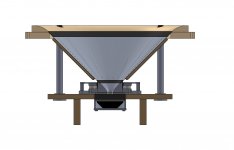
Current iteration. Not all fasteners are shown.
The "basket" is aligned to the aluminum mounting plate using two dowel pins. I had previously used a bunch of shoulder screws all over the place for location, but I figured it would be more effective and more economical just to use two pins for location, and regular screws for fastening.
The "basket" is aligned to the aluminum mounting plate using two dowel pins. I had previously used a bunch of shoulder screws all over the place for location, but I figured it would be more effective and more economical just to use two pins for location, and regular screws for fastening.
Attachments
Finally picked up the DE250. Man, it's definitely a surprise to see your first (ferrite) compression driver. Much bigger and heavier than a direct-radiating tweeter.
Unfortunately, I need to pick up a battery for my digital caliper before I can start verifying dimensions. Once I do, I'll start sending out parts for fabrication.
Unfortunately, I need to pick up a battery for my digital caliper before I can start verifying dimensions. Once I do, I'll start sending out parts for fabrication.
I haven't died! Life's just carried me away...
Reading through this thread makes me a little sad since 80% of the posts are my own.
I did, however, make a conceptual breakthrough regarding the surround. I was disappointed with how frustrating it was going to be in order to get a strip of rubber to be naturally angled inward as shown in the earlier pics (it has to be cut and formed the same way as the cone, i.e. "rolled").
I don't have any CAD on my current computer but I'll post pics as soon as I have a chance. The new method gets me a practically-100% symmetrical F(x) from the surround, is much easier to produce and install, and to top it off, allows a much greater selection of foams.
- Status
- This old topic is closed. If you want to reopen this topic, contact a moderator using the "Report Post" button.
- Home
- Loudspeakers
- Multi-Way
- 18" 90-deg OS WG coaxial (design)