[In order to make the cones easier to fabricate, I'll be changing the cone profile from OS to conical. After the first few inches, it looks like there is very little difference, and the benefit is that I will be able to take a sheet of aluminum and form the cone by rolling a cutout
I don't know if you are currently using Solidworks for your 3d CAD models. There is a sheet metal "flatten" function that will give you the exact template to cut the cone from a 2d sheet. I used this to make the cut pattern for a tractrix horn and it worked perfectly.
Yes, I am. I didn't think of that. D'oh!I don't know if you are currently using Solidworks for your 3d CAD models. There is a sheet metal "flatten" function that will give you the exact template to cut the cone from a 2d sheet. I used this to make the cut pattern for a tractrix horn and it worked perfectly.
Also, it looks like not only will I have a make a mandrel, I'll have to make two of them. Details to come.
Yes, I am. I didn't think of that. D'oh!
Also, it looks like not only will I have a make a mandrel, I'll have to make two of them. Details to come.
Note that the 3d object has to be generated via lofting a 2d line with a specified thickness. You cannot "unroll" and flatten a conventionally extruded 3d object. Watch some YouTube videos first - easy once you get the process down.
454Casull, Do you have listening and measurement experience with large diameter coaxial speakers? I mainly see them sold for on-floor stage monitors. I use one for my HT center channel 80-20KHz speaker with excellent results at low SPLs.
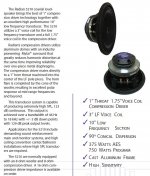
Personally, I would probably first experiment with a high quality coaxial speaker like the Radian 5215Neo which has a machined throat+short_horn that smoothly interfaces the 2" compression driver to the moving cone horn. I would probably add a pair of $200 Peavey LoRider18 model 560600 woofers in a side-firing counter-force arrangement for high efficiency bass below 100Hz in a separate box. I would probably try a few of Gary Dahl's large radius MDF edges for diffraction control. DECISION: 1" vs. 1.4" vs. 2" compression driver. 2" appears most common for 15" & 18" coaxials that favor 500Hz-700Hz Xover.
Easy instrument test: summation of a high frequency sine tone + a low beat-frequency sine tone to listen and measure intermodulation from movement of the 15" horn/cone.
Difficult listening test: A soprano voice with a piano for purity of vocal tone with IMD..Kathleen Battle..Diana Krall. Copland's "Theme for a Common Man" with horns above bass drums and GONG. etc...
The experiments could help a blank sheet construction, or you might be able to use the Radian 5215Neo frame+motor with an extension frame for the wider, deeper cone plus new surround.
Attachments
Last edited:
In order to make the cones easier to fabricate, I'll be changing the cone profile from OS to conical.
If conical dispersion is your new goal.....
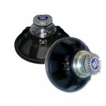
Both the 15" Radian coaxial with a 2" compression driver, and the 10" Radian coaxial with a 1" compression driver have a conical flare throat machined into the center of the steel woofer pole piece. The horn flare is compleded by the woofer cone. Both claim a 90degree conical dispersion.
You could add a fixed extension conical horn section to the speaker frame in order to experiment with directivity control vs. horn length/size.
The 10" Radian 5210 with the 1" compression driver will reach ~18Khz. Experiments with a non-moving extension horn could test if improved polar pattern control is possible.
In my coaxial, I can easliy hear ugly modulation from a high frequency sine wave + low frequency sine wave, but I do not feel psycho with normal music. No 666 the Devil made me do it problems .... so far.
Buy or borrow a Radian coaxial and run a few test! I could not find a 15" or 18" coaxial speaker with a 1" compression driver plus 1" machined pole piece to compare with the Geddes OS designs.
Attachments

The throat is still machined according to the OS profile. The maximum variation between a conical profile and the actual OS profile, after the point of discontinuity, measured out to less than 1 mm if I recall correctly.If conical dispersion is your new goal.....
I tried looking for pics of those Radian units and could not find any good ones.
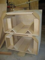
Latest progress pic attached.
Attachments
I'm still not sure how to make the sandwich cone. All other problems I can see can be solved by throwing money at them, but this... unless I have someone else do it. Not a preferred option.
Either I roll up all three layers individually and epoxy them together, or I make a flat sandwich and roll it into a cone in one piece. With the former, the concern is making sure everything stays in shape and has good contact throughout the entire surfaces, but with the former, I'm not sure I'll be able to roll the cone once the sandwich is made.
Either I roll up all three layers individually and epoxy them together, or I make a flat sandwich and roll it into a cone in one piece. With the former, the concern is making sure everything stays in shape and has good contact throughout the entire surfaces, but with the former, I'm not sure I'll be able to roll the cone once the sandwich is made.
Member
Joined 2003
With a female mold? The pieces may not line up properly - that is, assuming they are made by rolling up a curved section into cones. The seam is critical.Vacuum bagging?
Have an idea:
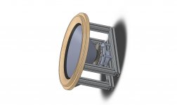
1) Make up a female mold. Layered MDF cut on a lathe should do the trick. This can also accept attachments to e.g. jig up the voice coil and spider assembly steps.
2) Laser-cut the outside (visible) aluminum sheet, profiled for conical roll-up. Each end should have a slight excess length to produce an overlap, and this overlap should have two alignment holes on it, also laser-cut, to ease assembly.
3) Wrap the sheet around the mold, taking care to match the pinholes together.
4) Apply epoxy (sparingly, to prevent squeeze-out) between the overlapping ends. A long wooden block with some firm rubber foam on it could potentially be clamped to the mold, pressing down on the overlap, in order to guarantee that the joint conforms to the conical profile of the mold.
At this point, the first layer is done and with it being on the mold, we can keep it rigid which makes it a lot easier to work with.
5) Laser or manually cut the sandwich material, again profiled for conical roll-up. In this case, I believe that honeycomb is actually preferable to foam for its ease in hand-forming, as no heat is required. Either Nomex or flex-core aluminum would do the trick. A thickness of either 1/8" or 1/4" would be acceptable.
6) Test-fit the honeycomb on the first layer. If everything lines up, tape the two ends together or otherwise attach the honeycomb to the first layer in such a way that intimate contact is made all around the cone. Cyanoacrylate glue might also be handy.
7) Depending on the average gap spacing between the honeycomb cells and the first layer, choose either low-, medium-, or high-viscosity high-strength epoxy. The closer the cell edges are to the first layer, the thinner the epoxy can be.
8) Using a thin artist’s brush, paint the inside bottom edges of each cell with the epoxy, ensuring a healthy joint all around the cell to the first layer. Each and every cell needs this treatment, so yeah, this might take weeks and a handful of brushes.
9) Laser out the inside (non-visible) aluminum sheet, but instead of making it a continuous cone, make it into a number of radial slats. This will make it easier to assemble to the honeycomb.
10) Using high-viscosity epoxy, paint the outside edges of every cell underneath one slat. The amount of epoxy required depends on how discontinuous the outer surface is, relative to a conical surface. Once fully wetted, the slat goes on and is held in place either with a weighted bag or with a clamped block.
11) Repeat 10) until all the slats are on.
12) The seams between each slat can be painted over with epoxy, just to be on the safe side.
I did consider heat-activated films, such as this one:
Adhesives, Tapes, Reclosable Fasteners & Fabricated Parts : 3M? Thermal Bonding Film AF111, 40 in x 36 yd, 1 per case
But, it's too soon to say whether or not the thickness would be sufficient to bridge all the gaps. Any unattached cells would contribute nothing to the overall strength, or worse, buzz during playback.
To save myself the trouble of finding an appropriate spider, and also for shats and giggles, I’m working with an acquaintance to laser-cut a spider out of stainless steel. I’ve designed the initial model (pics later) and have come up with the following criteria:
1) The compliance (Cms) has to be constant within +/- 10% around the zero point for a maximum displacement of 1 mm (one-way)
2) Cms has to be within +/- 20% of 4x10^-5 m/N at zero excursion. This is for an arbitrary selected Fs of 40 Hz, though I don’t see any issues if it is looser than this.
3) The frequency of the first resonance or vibration mode must be 1.5 kHz or higher (i.e. one octave above the expected low-pass).
4) The maximum stress given a displacement of 1 mm (one-way) must not exceed the fatigue limit (for e.g. 304 SS), for longevity of operation.
5) A force of 2.2 N (the estimated dead weight) acting radially on the center produces a static radial displacement of not more than 0.1 mm, to allow for a tighter coil gap.
If anyone has any ideas to improve it, let me know.
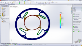
Attached. Remarks:Initial results from the FEA analysis show that the first design won't work, but end-game might be very promising. Pics to come soon.
1) It's actually too stiff, which makes my Fs basically double what I want it to be. Still, this doesn't mean much given that the driver only needs to go down to about 300 Hz or so.
2) There's some slight twisting during excursion.
3) The "pushing" off axis due to the weight of the cone assembly is very small, at less than 0.1 mm.
4) Vibration analysis is not yet completed. Still hoping for the natural frequency to be above 1.5 kHz.
Credit goes to Grasshopper Machine Werks LLC for helping with the analysis. Please do not reproduce this image without crediting the aforementioned company.
Attachments
Last edited:
1) Would milling (or sanding) it down be an option to loosen it up?Attached. Remarks:
1) It's actually too stiff, which makes my Fs basically double what I want it to be. Still, this doesn't mean much given that the driver only needs to go down to about 300 Hz or so.
2) There's some slight twisting during excursion.
2) Does the cone surround eliminate the twisting, or does it still twist with cone and voice coil attached to the basket?
It is of course feasible to reduce the dimensions of the metal in order to loosen it up. However, the most effective way, given that it is desirable to minimize the mass, is to make the bending portions (the "legs") thinner rather than narrower. Linear vs cubic stiffness growth, etc.1) Would milling (or sanding) it down be an option to loosen it up?
2) Does the cone surround eliminate the twisting, or does it still twist with cone and voice coil attached to the basket?
If manually attacking the metal to make it smaller, you risk distorting it permanently, or doing it asymmetrically, in which case during excursion you have additional twisting and tilting. So, the best way is just to make it with smaller dimensions to begin with.
A slight digression - the designer suggested going with a spring steel so that there is more headroom w.r.t. fatigue stress, while I had originally suggested 304 SS as the material.
The cone surround, being as soft as it is, won't eliminate/prevent all the twisting. I would much rather design the spider so that it doesn't twist during excursion, so that the surround doesn't experience any non-axial deflection. It should be a fairly simple fix - make the legs with double-opposing bows instead of unilateral bows.
EDIT: Just so we're on the same page, that image is a simulation of a CAD part. It's not a laser scan of an actual piece.
Last edited:
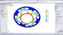
As luck would have it, we are all on the same page.Well this is an interesting and difficult project, count me subscribed. I suppose you'd need to either double the bends in the legs or double the number of legs and have half of them bend the other direction to avoid a twist.
The extra holes in the new revision are for holding the part down, if it is being tool-cut rather than laser-cut.
The spring characteristics appear to be bang-on now, but unfortunately the natural frequency is only 960 Hz, which is too close to the passband for my liking. We are working on raising it now.
The nice thing about having this piece screwed to the mounting structure, rather than glued in, is that the voice coil can be shimmed after everything is in place. That means that the sag due to the weight of the coil assembly can be "zeroed-out" once the speaker is in its final position, to allow for maximum coil gap clearance.
Credit goes to Grasshopper Machine Werks LLC for helping with the analysis. Please do not reproduce this image without crediting the aforementioned company.
Attachments
- Status
- This old topic is closed. If you want to reopen this topic, contact a moderator using the "Report Post" button.
- Home
- Loudspeakers
- Multi-Way
- 18" 90-deg OS WG coaxial (design)