Thanks Apex.....will keep you posted on my progress.......
Regards,
Macd
You can find more information about NX14 in thread:
http://www.diyaudio.com/forums/solid-state/164093-100w-ultimate-fidelity-amplifier-28.html
Regards
NX-14 Completed
Hi Apex,
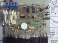
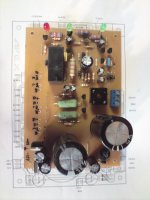
I completed my first NX-14 yesterday, I post some pics here. I also completed the PSU + Protect. I have a problem with my NX-14. On power up, +30V-30V used, I measure +10V dc on the output. I cannot set the bias current. Turn the pot but nothing happens. There is no short as my power supply is not limiting. I will do some troubleshooting tonight and double check every thing....will keep you posted.
Regards
Macd
Hi Apex,
I completed my first NX-14 yesterday, I post some pics here. I also completed the PSU + Protect. I have a problem with my NX-14. On power up, +30V-30V used, I measure +10V dc on the output. I cannot set the bias current. Turn the pot but nothing happens. There is no short as my power supply is not limiting. I will do some troubleshooting tonight and double check every thing....will keep you posted.
Regards
Macd
Attachments
Last edited:
no...........I have to connect a seperate wire from input ground to power ground.
Connect the Signal Ground (Input Ground) to the main Audio Star Ground.
Connect the Power Ground to the main Audio Star Ground.
Connect the Speaker Return to the main Audio Star Ground.
Connect Chassis to main Audio Star Ground.
RE..
Thanks AndrewT for the reply.
I will make this connections in my final assembly when I assemble the units in the case. Can I connect a 100R to power ground for my testing phase as apex suggested in his other threat. Is it okey or do I have to connect all to main audio star ground. Can I use my ground on my PCB for my main audio ground during my testing phase?
Regards,
Macd
no.
Connect the Signal Ground (Input Ground) to the main Audio Star Ground.
Connect the Power Ground to the main Audio Star Ground.
Connect the Speaker Return to the main Audio Star Ground.
Connect Chassis to main Audio Star Ground.
Thanks AndrewT for the reply.
I will make this connections in my final assembly when I assemble the units in the case. Can I connect a 100R to power ground for my testing phase as apex suggested in his other threat. Is it okey or do I have to connect all to main audio star ground. Can I use my ground on my PCB for my main audio ground during my testing phase?
Regards,
Macd
Hi Apex,
I completed my first NX-14 yesterday, I post some pics here. I also completed the PSU + Protect. I have a problem with my NX-14. On power up, +30V-30V used, I measure +10V dc on the output. I cannot set the bias current. Turn the pot but nothing happens. There is no short as my power supply is not limiting. I will do some troubleshooting tonight and double check every thing....will keep you posted.
Regards
Macd
Amplifier must have connection from input GND to PSU GND or you can put 10R resistor in parallel with C13 (100nF) for the test.
If you can't set the bias current, replace R17 1k with 470R. Trim pot 1k set at maximum value (1k), turn it down to set bias.
Regards
Last edited:
For +/-30V resistor 1k2/2W on protect pcb must be replaced with 470R or lower if you want 24V on relay, or you can use 12V relay and find serial resistor value to get 12V on relay.
Thanks Apex.....but I have a +/-50V 10A toroid for my amp.I tested it with my PSU+Protect and all seems okey.... I connect this amp to +/-30V from my bench PSU to test amp first and if everything is okey.....I will connect amp to
PSU+Protect.
Macd
RE... NX-14 Completed
Hi Apex,
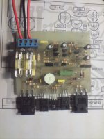
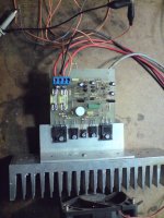
I connected 10R in parallel with C13(100nF) as you suggested.....DC on output is gone. Replace R17 1K with 470R and still cannot set the bias current. Turn pot and nothing happends.....I then connected test load.....put some music on and check with my scope the output....sound was playing. Mounted the amp on heatsink......put test speaker on...connect sound and sound was playing.....one problem.....the sound is a bit distorted......I do not know if this is because of the bias problem or the low voltage that I am using....(+/-30V)......I want to connect my transformer and PSU+Protect today and test again.....Do you have any suggestions on how to fix bias problem......do you have a schematic with voltages for me to do some measurements........can I go forward and connect my transformer to with this amp.......I am planning on building the second channel this weekend an will see if I get the same results.....will keep you posted on om progress.....
Regard,
Macd
Hi Apex,
I connected 10R in parallel with C13(100nF) as you suggested.....DC on output is gone. Replace R17 1K with 470R and still cannot set the bias current. Turn pot and nothing happends.....I then connected test load.....put some music on and check with my scope the output....sound was playing. Mounted the amp on heatsink......put test speaker on...connect sound and sound was playing.....one problem.....the sound is a bit distorted......I do not know if this is because of the bias problem or the low voltage that I am using....(+/-30V)......I want to connect my transformer and PSU+Protect today and test again.....Do you have any suggestions on how to fix bias problem......do you have a schematic with voltages for me to do some measurements........can I go forward and connect my transformer to with this amp.......I am planning on building the second channel this weekend an will see if I get the same results.....will keep you posted on om progress.....
Regard,
Macd
Attachments
Hi Apex,
I connected 10R in parallel with C13(100nF) as you suggested.....DC on output is gone. Replace R17 1K with 470R and still cannot set the bias current. Turn pot and nothing happends.....I then connected test load.....put some music on and check with my scope the output....sound was playing. Mounted the amp on heatsink......put test speaker on...connect sound and sound was playing.....one problem.....the sound is a bit distorted......I do not know if this is because of the bias problem or the low voltage that I am using....(+/-30V)......I want to connect my transformer and PSU+Protect today and test again.....Do you have any suggestions on how to fix bias problem......do you have a schematic with voltages for me to do some measurements........can I go forward and connect my transformer to with this amp.......I am planning on building the second channel this weekend an will see if I get the same results.....will keep you posted on om progress.....
Regard,
Macd
Low voltage can't be a problem. You can do some measurements:
DC voltage on resistors
R4 (560R) 0,6V
R14,R15 (220R) 1,2V
R20,R22 (220R) 3,5V
Regards
Hi Apex....
If these voltages are okey......can I go forward and connect my transformer.....I must say that the sound is very good.....just that the bass or low freq distorts a little.....any other suggestions......to fix my bias problem.....
Macd....
Yes, but try without 10R, use separate wire for input GND, and put zobel network on speaker output (5R6/2W, 100nF).
Last edited:
R1-1k
R2,R11-22k
R4,R6,R7,R8,R16-560R
R5,R10,R14,R15,R17,R18,R19-220R
R9,R12,R13-100k
R20,R21,R22,R23-0R33 5W
C1-10uF/25V ELKO
C2-100pF KER
C3-1500pF KER
C4,C5,C11,C12-2,2uF/63V ELKO
C6-100uF/25V ELKO
C7-330pF KER
C9,C10-220pF KER
C8-100nF MKS
D1,D2,D3-1N4148
Q1,Q2,Q3-2N5401
Q4,Q5,Q7-BC547
Q6-BC557
Q8-MJE340
Q9-MJE350
Q10-BD139
Q11,Q12-BDW84D
PCB size:62,5x82,5mm
Q13,Q14-BDW83D
Hi Apex,
Is it possible to replace BDW83D/BDW84D with TIP35c/TIP36c ?? if not any preferences?
what is the damping factor of this amp?
How about the power dissipation of this under 4 ohms load (to select a proper heatsink)??
thanks and best regards,
Lycanlk
Hi Apex,
Is it possible to replace BDW83D/BDW84D with TIP35c/TIP36c ?? if not any preferences?
what is the damping factor of this amp?
How about the power dissipation of this under 4 ohms load (to select a proper heatsink)??
thanks and best regards,
Lycanlk
BDW83D/BDW84D is darlingtons, and can not be replace with TIP35C/TIP36C, but you can use many darlington pairs: TIP142/TIP147... go to thread http://www.diyaudio.com/forums/solid-state/164093-100w-ultimate-fidelity-amplifier-33.html for more info.
Dissipation with 4R load on full power will be about 50W.
Regards
Last edited:
Apex,
Thanks for the reply.. I'm very familiar with TIP142c/TIP147c and also I have a couple of TIP33c/TIP34c Darlingtons.. Can I use them ?
I selected this amp specially for a subwoofer (JBL 12 inch 350W).
I will follow the link you have mentioned. I have already followed many links started by you and I appreciate your contribution to the society.
I love to build your H900 too when I get a chance.
Thanks and best regards,
Lycanlk
Apex,
Thanks for the reply.. I'm very familiar with TIP142c/TIP147c and also I have a couple of TIP33c/TIP34c Darlingtons.. Can I use them ?
I selected this amp specially for a subwoofer (JBL 12 inch 350W).
I will follow the link you have mentioned. I have already followed many links started by you and I appreciate your contribution to the society.
I love to build your H900 too when I get a chance.
Thanks and best regards,
Lycanlk
TIP33C/TIP34C is not darlingtons, U can use BDX33C/BDX34C with +/-35vdc.
Regards
hi,
I built the KELVIN amp with TIP142/TIP147. Amp works but there is a huge hum and heating more than I expected. Is this because I used 0.47R/5W instead of 0.33R/5W? and also I used 1uf mylar for C4 and C6 (original value is 2.2u/63v eletro), 100n for C12 and C11 ( railing caps - original value is 2.2u/63v electro)
I used several power supplies, voltage from +/-30 to +/-50 but still the hum is there. I will send some pictures of my amp soon so may be you can help me with that.
regards,
Lycanlk
hi,
I built the KELVIN amp with TIP142/TIP147. Amp works but there is a huge hum and heating more than I expected. Is this because I used 0.47R/5W instead of 0.33R/5W? and also I used 1uf mylar for C4 and C6 (original value is 2.2u/63v eletro), 100n for C12 and C11 ( railing caps - original value is 2.2u/63v electro)
I used several power supplies, voltage from +/-30 to +/-50 but still the hum is there. I will send some pictures of my amp soon so may be you can help me with that.
regards,
Lycanlk
Something is wrong, amp must work humless and without unexpected heating. Do you measure BIAS current and DC offset on amp out. Post pictures and I help you.
Regards
- Home
- Amplifiers
- Solid State
- 150W MOSFET Amplifier with IRFP250x2