Archimedes said:Can anyone please tell me how much inductance is necessary for the input and output chokes ? I chose values that I saw commonly used. Is there formulae for this purpose so that I don't have to do thumb sucking ?
Can I please ask the gurus out there to take a look at the attached spreadsheet and give me any feedback if possible.
I use it whenever I wind trafo's.
PS. Do you think it will be more feasible to wind a 305.9mm Ac (I have this too) or will the 152.4 Ac give me the required 1000W ?
thanks everyone for your input! [/B]
Are there any formulae that I can use to calculate how much inductance is needed ? Those of you guys that have downloaded the attached spreadsheet what do you think of it ? Is it accurate enough or does it need minor tweaking ?
Archimedes said:
Are there any formulae that I can use to calculate how much inductance is needed ? Those of you guys that have downloaded the attached spreadsheet what do you think of it ? Is it accurate enough or does it need minor tweaking ?
Hi All
I have been away for a while. Is there no one on this forum that is able to assist me with my requests ?
")
To those who have downloaded my transformer calculator did it prove helpful or useless ? Any feedback is most welcome.
Just an update on the 12V to +/-63V issue. I have decided to redesign the entire board as I had to redo a transformer and the old board has seen much abuse from soldering and desoldering etc. I have just completed making my own UV light box as well as a glass etching tank complete with pump and heater. Got the Positiv20 and am now ready to do this over the weekend. I got tired of the old Toner ironing method as this proved to be very unsatisfactory.
Can't wait to assemble everything neatly and to test.
Archimedes said:
Are there any formulae that I can use to calculate how much inductance is needed ?
it's like asking "how to calculate the filtering cap size" its depends on how clean u want the output voltage to be ....
How to calculate filters?
I usually simulate them with some electronics software, and I adjust the values of the components until I get the desired frequency and phase plots. In order to do that, you must consider inductor series resistance, and including capacitor series resistance (ESR) is also desirable.
What you should look for is a reasonable attenuation (let's say 40dB or more) at the switching frequency, and what you should avoid is resonance peaking at the cut-off frequency.
Note that component values are not dependent on output current at all, but the saturation current rating of inductors must be higher than the peak current that they will have to handle. Also note that picking component values randomly usually yields very poor results (particularly when a too big inductor is chosen).
Thanks Eva... much appreciated.
What simulation software do you use if I may enquire? Lets assume you did not have this software or any other software would you still know how to calculate the filters?
I do apologise if I sound ignorant. Its just that my education in Electronics goes as far as Component technician level. I dont wish to stick at that level though.
Eva from your experience buliding high powered PSU's what are typical symptoms to look out for of too much or too little inductance in the output stage?
I would very much like to experiment with current mode control but have no idea where to begin. Any advice on where to start please
I would very much like to experiment with current mode control but have no idea where to begin. Any advice on where to start please
Too little output inductance yields high inductor ripple currents that reduce efficiency, increase switching and conduction losses, increase output ripple and may cause output capacitor overheating.
Too much output inductance solves all the previously mentioned issues, but it does at the expense of a very slow response to big load changes and a big resonance peak in the open-loop response of the control loop that makes loop stabilisation harder.
I think that the output filter of my 120A PSU has 4dB or so of peaking around 500Hz. Output capacitors make a total of 17.600uF with approx 0.0028 ohms total ESR, and output inductors make a total of approx 4uH (it changes due to progressive saturation) and estimated ESR is approx. 0.007 ohms (including transformer windings and synchronous rectification MOSFETs). Worst case current ripple may be nearly 25% of maximum output current (it changes a lot depending on input and output voltages).
Eva said:Too much output inductance solves all the previously mentioned issues, but it does at the expense of a very slow response to big load changes and a big resonance peak in the open-loop response of the control loop that makes loop stabilisation harder.
I think that the output filter of my 120A PSU has 4dB or so of peaking around 500Hz. Output capacitors make a total of 17.600uF with approx 0.0028 ohms total ESR, and output inductors make a total of approx 4uH (it changes due to progressive saturation) and estimated ESR is approx. 0.007 ohms (including transformer windings and synchronous rectification MOSFETs). Worst case current ripple may be nearly 25% of maximum output current (it changes a lot depending on input and output voltages).
Thanks Eva for the info. I hope you don't mind me asking questions that should seem obvious but please explain in laymans terms what you mean by "big resonance peak in the open-loop response of the control loop that makes loop stabilisation harder."
How do you view current through an inductor with your oscilloscope ? Do you have current probes ?
I noticed on some offline PSU's a small toroid mounted near the main transformer. There is about 2 turns of the main transformer wire that passes through this small toroid. I assume that this is used for the current mode control.
1. If this is so how does one estimate what size toroid to use ?
2. What should the turns ratio be on the secondary of the small transformer ?
3. Is this voltage then rectified and compared to something?
thanks for all your help
An update:
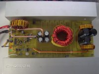
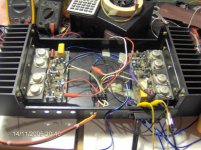
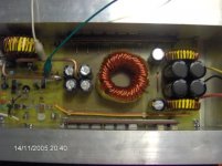
I have made a new board and this is what it looks like:
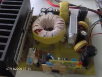
This is the old board compared to the new one:
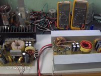
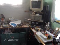
This what my setup looks like in my miniature lab
I have yet to populate the board completely but initial testing of the PWM chip and protection circuits are good.
Will post and update as soon as I have completed successfully.
I have made a new board and this is what it looks like:
An externally hosted image should be here but it was not working when we last tested it.
This is the old board compared to the new one:
This what my setup looks like in my miniature lab
I have yet to populate the board completely but initial testing of the PWM chip and protection circuits are good.
Will post and update as soon as I have completed successfully.
Thanks
The older prototype is working (was made about 1 year ago) but is the one I described that had the problem maintaining +/-63V at over 660W drawn from it.
In any event this board started out as a 3 x FET per side PSU and eventually after realising that the heat generated was just too much even for such a big heatsink and not to mention blowing up several sets of FETs with spectacular fire and smoke displays I then chopped off the part for the FETs and gate resistors and etched a small board the same size with 5 FETs per side. This worked quite well but the board was rather flimsy (epoxied) and not to mention ugly with all the late additions, soldering and desoldering etc.
I etched the new board last Sunday and I have completed drilling and now am slowly populating the board. I have tested the PWM chip and the protection circuit and everything is looking good. I need to mount the FETs and diodes and then begin testing. I need to juggle a full time job as a DBA and this unfortunately means I can only do a little at a time.
Help please!
Tests conducted this weekend proved satisfactory yet there are some issues I noticed:
1. The ringing frequency is in the order of 5MHz which required 15R and 680nF cap is series across the primary winding. This seemed to have squared off the waveform but their is still slight ringing noticeable at a 10% duty cycle. Is this normal ?
2. The output voltage regulation does not remain constant at 63V with no load but seems to decrease slowly to about 58V. Something I noticed was that the opto ILD55 seemed to be running a little hot as well as the resistors.When I kept my thumb against the case of the ILD55 the voltage went back up and seemed to stabilise. Any ideas ? Could the series resistors be too low a value ?
Update:
I have tested the converter with both channels connected and measured (33.34V/4R =>276Wrms per channel clipping. The output voltage from the converter held up pretty well considering that the Batt V fell to 10.5V measured at the bus bars in the converter. The total current pulled from the batt was 107A measured with the clamp (yes I know "Its not accurate") but the 2 x 50A fuses are still intact. The transformer though ran hot to a point where you cant keep your fingers on it for longer than 5sec. Heatsink for the converter was cool though. This test was conducted for a full 3mins (amplifier heatsinks was extremely hot).
In real music terms however I doubt any piece of music could place such a tremendous stress on the converter. I also doubt if anyone could sit in a car that has 540+Wrms of sound
A BIG BIG thanks goes out to Perry Babin, Eva, Pierre and others for their valued input. I think my initial problem was transformer saturation due to high flux levels.
There are still a few bugs to iron out.
Like when the power is removed from the remote-on the voltage jumps up for a split of a second to 80V + and then diminishes.
Attachments
- Status
- This old topic is closed. If you want to reopen this topic, contact a moderator using the "Report Post" button.
- Home
- Amplifiers
- Power Supplies
- 12V push pull SMPS