Joel said:Sorry to be a contrarian, but I don't like the idea of using a typical "matching transformer", or using capacitor coupling to it (parafeed).
With an 8k impedance driver like a plate-loaded 6SN7, I would simply use an off-the-shelf 6k-10k primary output transformer, and hook the headphones up to the 16 ohm tap. You could do push-pull, but an SE unit would also be fine at the microwatt levels needed.
There was an excellent thread here discussing just such a design, with good informative posts by PRR. Search for it.
Joel
Thanks Joel.
I didn't like the idea of being tied down to one output impedance. What if I want to use my tiny Sony headphones that measure 4 ohms? I assume that the solution you suggested would work over a range of different headphone impedances?
I'll look at that thread you suggested.
Glenn
How is this design with turntable use?
I'd now like to try this preamp with my turntable. It's a Denon DP-60L with a moving magnet cartridge (I lost track of my Signet moving coil cartridge after I broke the needle, doh!).
Will this preamp have enough gain to use with this, or do I need to add another stage? If I have to add another stage, can I add some switching to remove the added stage? I guess It would be easier to just add the input for the turntable before the new stage (if needed), and leave the existing inputs where they are.
Any desing ideas?
Thanks.
Glenn
Attachments

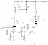
Other than rolling off the bass at 3.4Hz, what's the .047uF cap for?
Also, the 1M resistor that will alledgedly save you from catastrophe should the wiper go bad on the pot - if the wiper goes bad, you'll get no music... which would be a pretty good indication that something is wrong. Does anybody think they'd be running their amp for minutes or hours with an open pot?
In any event, a 6SN7, even with zero bias, is simply not going to destroy itself with 48.5k of series resistance. The extra resistor is silly, IMO.
Joel
Joel said:Other than rolling off the bass at 3.4Hz, what's the .047uF cap for?
Also, the 1M resistor that will alledgedly save you from catastrophe should the wiper go bad on the pot - if the wiper goes bad, you'll get no music... which would be a pretty good indication that something is wrong. Does anybody think they'd be running their amp for minutes or hours with an open pot?
In any event, a 6SN7, even with zero bias, is simply not going to destroy itself with 48.5k of series resistance. The extra resistor is silly, IMO.
Joel
I was trying out the variation on this circuit that BernardB posted here (bottom circuit):
http://www.diyaudio.com/forums/showthread.php?s=&threadid=67433
I thought the .047uF input cap was to prevent any DC from the input (not that you should have any)? Other than that, I don't think having it roll the bass off at 3.4Hz is a bad thing. Kind of like a sub-sonic filter? In that case, why don't designers use something that rolls off the bass at around 10-18Hz? Most speakers can't reproduce that anyway, just curious.
I have also not changed the output cap to the suggested 5uF from the 1uF that I already have in there. Just waiting for them from Angela.
Glenn
SY said:You'll need a separate stage for phono to provide extra gain and RIAA equalization.
For the extra 2 cents that a resistor costs, use the 1M safety resistor.
Different Avitar SY??
Thanks for that information. Is it possible to incorporate an extra stage into this design, or am I looking at a new build? Any suggestions as to a design for another stage? Maybe a 12AX7?
Can I switch this new stage in or out of the circuit, or like I said just add another pair of RCA jacks for a phono input to this stage?
Glenn
I like to change my avatars every so often. This one is in honor of my kid's birthday.
Figure that you'll need a whole new build, unless you've got room for 3-4 more tubes. There are a lot of sources for good RIAA circuits- certainly, you can't go wrong by starting with one of the ones from Morgan Jones's book.
Figure that you'll need a whole new build, unless you've got room for 3-4 more tubes. There are a lot of sources for good RIAA circuits- certainly, you can't go wrong by starting with one of the ones from Morgan Jones's book.
Sorry, OT
Unlike most 5 year olds, Jimmy won't recognize most cartoon/merchandising characters, but he gleefully points out pictures of Wolfgang Puck. And at 2, he could name all the Iron Chefs, say what color they wore, what cuisine they represented, and what prop they would hold in their hand at the show intro. He's old enough to do plate arrangements now when I'm putting a nice dinner together. His musical tastes run to They Might Be Giants.
Greystone's not good enough for him; he's going to study at Bocuse if I have anything to say about it!
Apologies in advance to everyone for being OT 
That's Paul Bocuse in Lyon, right?
Very nice, I bet tuition is comparable to reputation
I almost went to NECI since I'm in Connecticut, but my Father had other ideas since he was the Dean of the school of Engineering at UCONN.
Good luck, at least you'll have someone to cook nice things for you when you retire.
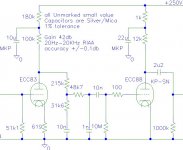
Back to tubes, I found this phono preamp schematic, and it looks simple.
Glenn
That's Paul Bocuse in Lyon, right?
Very nice, I bet tuition is comparable to reputation
I almost went to NECI since I'm in Connecticut, but my Father had other ideas since he was the Dean of the school of Engineering at UCONN.
Good luck, at least you'll have someone to cook nice things for you when you retire.
Back to tubes, I found this phono preamp schematic, and it looks simple.
Glenn
Attachments
Simple, yes, but high output impedance and high distortion. I would guess that the noise isn't so great, either. Rule of thumb- if there aren't at least three tube sections in an RIAA amplifier, there's a severe compromise somewhere.
Bocuse's school is just north of Lyon (a suburb called Ecully). I used to date their International Studies director, so I have some familiarity with them. I'm completely self-taught as a cook, but have managed to eke out one or two edible dishes in my day. Jimmy's got some work ahead of him if he wants to impress the old man.
Bocuse's school is just north of Lyon (a suburb called Ecully). I used to date their International Studies director, so I have some familiarity with them. I'm completely self-taught as a cook, but have managed to eke out one or two edible dishes in my day. Jimmy's got some work ahead of him if he wants to impress the old man.
DC on output for phones?
Hi all-
I'm back to the 6SN7 preamp/headphone amp.
Please refer to post #82 for the schematic.
I installed a DPDT switch for the outputs to switch between the RCA jacks and the headphone jack. The RCA uses a 1uf electro cap, and the headphone jack uses a 220uf electro.
The wierd thing is, I'm getting ~130VDC on the output of the 220uf capacitors for the headphones! When I switch to the 1uf caps for the RCA line out jacks, I get 0VDC at the jack.
Any ideas as to what is going on?
Why would the 1uf block the DC, and the 220uf not?
I don't think I want to plug my headphones into 130V!
Glenn
SY said:Well, you do have a 22 second (probably more) time constant there. It might take a while to settle to zero.
Yeah, and if you plug in your headphones during that time, pop goes the weasel. There is enough stored charge in 220uF to zap a little voice coil. This kind of circuit is risky for sensitive headphones. You could put a shorting relay with a timer on the output to provide a time delay for the big output cap to charge. Or, put in maybe a 2K shunt ground reference resistor instead of the 100K to speed up the charging time. The 2K in parallel with your 32 to 300 ohm headphones won’t significantly reduce levels or increase distortion. Then, and this is a bit brutal, you can add a pair of series zeners (back-to-back) across the output line to clamp start-up transients. For Sennheisers maybe a pair of 8.2 volts zeners; for Grados, lower.
Joel said:Also, the 1M resistor that will alledgedly save you from catastrophe should the wiper go bad on the pot - if the wiper goes bad, you'll get no music... which would be a pretty good indication that something is wrong. Does anybody think they'd be running their amp for minutes or hours with an open pot?
That's not the point. It's not the presence or absence of music that we’re worried about; it's the sudden large step-function jump in the DC levels as the grid bias goes from a ground reference via the pot suddenly to an open condition. When open, a grid will find a voltage point of equilibrium where positive and negative grid currents cancel. This is typically between -1.0 and 0 volts of equivalent grid bias. If your grid bias is normally 3 or 4 volts (a wild guess - I didn’t do the load lines on the schematic in post #82), you just snapped a 3 volt transient into your input. The output, of course, will react to that with gain. With headphones on, it might sound like a lightning bolt in your ear. Even worse, if the pot is intermittent, as you turn it you’ll get a series of makes and breaks, and you’ll experience multiple lightning bolts per second. More than one tweeter has been lost through the decades due to intermittent volume pots.
I agree with SY. For a couple of cents, keep the safety resistor even if you drop the input coupling cap.
Thanks for the answers.
Yes, I did notice that the DMM I had on the circuit was headed down slowly. I guess I'll go back and give it time to zero-out.
I'm probably going to use a transformer as previously discussed in this thread, but I'm experimenting for now.
That's the fun of DYI and learning for a newbie like me
Now if I can decide on OT's for my SE KT88 project I can finish that also! I'm undecided as to who's transformer to use, the "new" Hammond 1628SEA, or the Edcor.
Thanks again.
Glenn
SY said:Not enough tubes. Take a look at Jones's ECC88-based phono preamp.
Hi, any chance of a url for this phono?
Cheers
Andrew
Brian Beck said:
Thank you! I see our local library has two copies so I will take a look today.
Kind regards
Andrew
- Status
- This old topic is closed. If you want to reopen this topic, contact a moderator using the "Report Post" button.
- Home
- Amplifiers
- Tubes / Valves
- 12AY7/6SN7 preamp PSU check