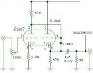
"Is this correct for the diode installation?"
No, the 1N4007 should be reversed. The cathode of the diode should be to the cathode of the tube. When the tube warms up, the voltage at the tube's cathode will be greater than at its grid, reverse biasing the diode and removing it from the circuit.
Also, if you plan on using this circuit to run typical 300 ohm headphones, you will need an output capacitor at least 100uF. For 150 ohms, at least 220uF, etc.
Joel
Ok, try this on for size.
Joel-
What if I want to run both headphones and an input to a power amplifier for this preamp? Can I split the signal path after the cathode, and go to 2 different capacitors? One for an RCA output for a power amplifier, and one for a headphone jack? 100uF-220uF we're now talking electrolytic caps only right? I don't think I've ever seen a 100uF 250V poly cap.
Thanks for your help guys.
Glenn
Attachments
Re: "Can I split the signal path after the cathode, and go to 2 different capacitors?"
Hi Joel-
Do I have to use a switch? Is there something wrong with just leaving one circuit open when not in use?
Ok, here's a basic question about the value of the output capacitor. What does the value of this capacitor do to the output of this preamp? Does it control impedance, or is it frequency related. I'd like to understand what effect the value has on the circuit.
Thanks
Glenn
Joel said:Yes, that's exactly what you would do. Use a SPDT switch, with one leg going to a 220uF electrolytic, and the other to a film cap of 0.22uF or larger.
Joel
Hi Joel-
Do I have to use a switch? Is there something wrong with just leaving one circuit open when not in use?
Ok, here's a basic question about the value of the output capacitor. What does the value of this capacitor do to the output of this preamp? Does it control impedance, or is it frequency related. I'd like to understand what effect the value has on the circuit.
Thanks
Glenn
If you don't cut off the other capacitor not being used, it hangs off the output directly connected to the cathode. That makes a great antenna.
The output capacitor, besides blocking DC, forms a filter with the resistance of the load in parallel with the 1M resistor to ground.
The -3dB point of this filter is 1/(2Pi*R*C)
Joel
The output capacitor, besides blocking DC, forms a filter with the resistance of the load in parallel with the 1M resistor to ground.
The -3dB point of this filter is 1/(2Pi*R*C)
Joel
Re: "Is this correct for the diode installation?"
Good morning all (it's 8:40AM here)-
I measured my headphones (vintage 1983 Yamaha studio), and they are ~130 per side. I assume the 220uF elect cap would be ok for these, yes? How do you calculate the output capacitor value for a given headphone load?
Thanks.
Glenn
Joel said:
Also, if you plan on using this circuit to run typical 300 ohm headphones, you will need an output capacitor at least 100uF. For 150 ohms, at least 220uF, etc.
Joel
Good morning all (it's 8:40AM here)-
I measured my headphones (vintage 1983 Yamaha studio), and they are ~130 per side. I assume the 220uF elect cap would be ok for these, yes? How do you calculate the output capacitor value for a given headphone load?
Thanks.
Glenn
Joel said:
The output capacitor, besides blocking DC, forms a filter with the resistance of the load in parallel with the 1M resistor to ground.
The -3dB point of this filter is 1/(2Pi*R*C)
Joel
This is another question I had about this circuit. I added the 1M pulldown resistor to the output, originally this circuit did not have this. Can I still prototype the circuit with the 1uF capacitor called for, or do I need to change this value initially now. I will be trying this circuit out by connecting it to a solid state power amplifier initially (vintage Marantz). Or maybe I shouldn't even use the 1M resistor at all since I don't plan on unplugging anything while the unit is powered on.
Thanks
Glenn
Use the 1M resistor. For a nickel, you can forever not worry about accidental bangs and pops if an output connection accidently goes intermittent or pulls out.
For a solid state amp, the load impedence is generally 10-20K. I'll leave the calculation of the capacitor to you.
For a solid state amp, the load impedence is generally 10-20K. I'll leave the calculation of the capacitor to you.
It's not phase shift, it's polarity reversal. If one worries about it, swapping speaker wires (or doing any other polarity reversal in the signal chain) cancels it out perfectly.
Worry more about absolute polarity in your source material. That's something that you won't know and can't control, other than by listening and guessing.
Worry more about absolute polarity in your source material. That's something that you won't know and can't control, other than by listening and guessing.
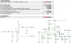
Output impedance calculations
Okay SY-
Here's my attempt at calculating output impedance for this amplifier. I looked at Mr Aiken's site (he's a great resource)http://www.aikenamps.com/Equations.htm
I just can't seem to match his circuit calculations to mine. My circuit (Joel's) is on the right. I guess it's because the circuit I'm using is different from his example that I'm having trouble.
For instance, he uses the resistance RI in parallel with the plate resistance even though the output is taken off the cathode, is this right? I'm also not sure if I use the 1M resistor as the input resistance of the next stage, or the resistance of the headphones (130 ohm), or the two added together?
Attachments
I'm not understanding the question very well- sorry, not much sleep the past few days. In any case, the output Z of a cathode follower will be very close to 1/gm. For a 6SN7 running at 5-6mA, the gm is roughly 2.5mA/V, so the output impedance will be roughly 400 ohms. Is that what you're asking?
For 130 ohm headphone drivers, you might want a lower source impedance than that, or consider using a step-down output transformer.
For 130 ohm headphone drivers, you might want a lower source impedance than that, or consider using a step-down output transformer.
Thanks for looking at that post Sy.
Can you briefly explain "lower source impedance"?
Is this the impedance of the circuit, or the device connected to the circuit ie. a CD player, tape deck, etc.?
Also, this circuit does not have a capacitor on the input, is that a big deal? I guess it doesn't matter as long as there is no DC on the input. I've also seen some of these preamps with a 1M resistor on the input as well.
Sorry for all the questions, and thanks for your time.
Glenn
Let's start easy with a quick homework assignment. Are you familiar with the concepts of Thevenin and Norton eqivalents? If not, look 'em up in any electronics text, try to work a couple of examples, and we'll discuss.
If you are familiar with them, the source impedance is the Thevenin equivalent resistance of the cathode follower's output, i.e., from the point of view of the load, the cathode follower looks like a Thevenin source with a resistance of 400 ohms.
If you are familiar with them, the source impedance is the Thevenin equivalent resistance of the cathode follower's output, i.e., from the point of view of the load, the cathode follower looks like a Thevenin source with a resistance of 400 ohms.
SY said:Let's start easy with a quick homework assignment. Are you familiar with the concepts of Thevenin and Norton eqivalents? If not, look 'em up in any electronics text, try to work a couple of examples, and we'll discuss.
If you are familiar with them, the source impedance is the Thevenin equivalent resistance of the cathode follower's output, i.e., from the point of view of the load, the cathode follower looks like a Thevenin source with a resistance of 400 ohms.
Fair enough.
I knew I should have done the double major (ME/EE) in College
")
I'm just a dumb ME, but I hope to remedy that soon!
Thanks.
Glenn
It's funny, but I can usually equate an electrical component to a mechanical one (It helps me think better that way).
For instance, a power supply capacitor is like a flywheel in an engine. It helps smooth out the revolutions of the crank every time the engine fires. I guess Physics is applicable across many fields of study. That's all it comes down to in the end anyway.
Oh, I forgot to ask, about the large electrolytic capacitors people use for the output of these headphone amps. Are these the snap-mount type ones I see on tops of some chassis? I'm looking for 220uF/450V units, and I don't see them in the "usual" radial or axial packaging. If they are, how do you mount these things? With a clamp like the very large ones for power supply filters?
Thanks.
Glenn
- Status
- This old topic is closed. If you want to reopen this topic, contact a moderator using the "Report Post" button.
- Home
- Amplifiers
- Tubes / Valves
- 12AY7/6SN7 preamp PSU check