Hi all, i've been trying to design a fairly high gain amp, (4 gain stages and a cathode follower) im using a +HT voltage of about 400v and i was thinking, what would be the best way to do this? i was thinking of cold biasing so that one side of the wave is clipped in one stage, and the other side in the next, or should i just centre bias everything and get as much gain as possible? the 2nd option seems the best but that would mean the output signal from the preamp would be a bit under 400vp-p this seems to be quite high, or is this normal?
I will add to that comment that so much gain is not desirable. Starting with, say, 100 mV of audio you can get all the distortion you can stand with a single gain stage. If you want overkill, put in two. But four? Might as well use a square wave generator.
And 400 V is way too much for those tubes. They run fine on 100V.
And 400 V is way too much for those tubes. They run fine on 100V.
Long tail pairs of 12AX7 in enhanced cathode coupled paraphase.
400 is not too much for those tubes, if we consider a tail voltage.
Paraphase Splitter Experiments
400V of output from the preamp is silly. As the output grids will
forward conduct long before that. Even cathode follower "driver"
grids will forward conduct and you will be in blocking distortion
(not the kind of distortion you are looking for)...
Last edited:
You should be able to get sufficient overdrive/saturation/sustain for most lead sounds from 3 stages BUT for the total shreader massively overdriven sound 4 stages is not that unusual. 4 stages are however difficult to design. You need interstage attenuators to make sure you are not overdriving the subsequent stages too much. you need big grid stoppers, not for their "stopping" function but to provide real HF roll off and limit grid current, you need to limit the amount of bass to prevent muddiness (small coupling caps and small cathode bypass caps) and noise becomes a serious issue. To control the noise you need to keep grid to 0v impedances low and the interstage attenuators can actually help with that.
Spend a little cash - Kevin O'Connors TUT6 (London Power, Canada) has the entire final chapter devoted to high gain preamps with lots of great information. The money you spend on the book will be saved in the first design.
I'm about to try something new - a jfet/triode cascode input stage (high gain, low noise) and just 2 gain stages following.
Cheers,
Ian
Last edited:
How to go about getting hi gain from a guitar preamp depends a lot on what kind of a sound you are after. If you're after a more modern sound, then go with lots of gain stages with attenuation in between them; for a classic rock sound, go with two, perhaps three (+ the PI), and some like that raw, supercompressed sound that you get with a very low number of stages (2 + SE output, think tweed champ).
I myself have found that the most useful and multi-purpose setup is the Trainwreck Express/Liverpool preamp. I've made a number of variations on this theme, and I feel they perform in a very wide range of music styles, from classic rock to 80's heavy metal. I've been pondering about changing the cathode RC's to diodes, and perhaps getting even a modern metal type of sound out of it - I will surely try this out at some point.
The Trainwreck has three gain stages + PI (in the purest form the output is the first to clip, but I haven't tried this one myself, as I live in an apartment and have no attenuator at the moment), each with a bigger cathode R than the previous. This leads to a very rich, harmonically complex sound.
Check out ampgarage.com if you're interested.
Check out ampgarage.com if you're interested.
http://www.blueguitar.org/new/schem/trainwreck/wreckxpr.pdf
I like a pentode for the 1st stage (brutal approach), I have found out that by tweaking the screen voltage you can get a wide variety of tones. If you do it wrong it will sound harsh and thin. Needs experimenting.
razorrick1293,
I re-read the KOC TUT6 section on high gain preamps to see what tricks he recommended and what circuits he liked.
He thought highly of this one (Carvin Legacy) describing it as;
"....well defined and refined. Plenty of gain on tap but without fizz or excessive girth".
http://www.webphix.com/schematic he...ven.com/newamps/carvin_legacy_vl100_vl212.pdf
Things in this circuit to note:
1) High current input stage for low noise
2) 50pF on g1 of stage 2 => 6.3kHz low pass into stage 2, at max gain
3) 1u cathode bypass on stage 2 => 106Hz Hi Pass
4) 1u cathode bypass on stage 4 => 72 Hi Pass (attenuates subsonic intermodulation products)
5) 1300Hz rolloffs on stage 2 and 4 to limit higher order harmonics and keep noise under control.
6) 950 Hz rolloff on stage 3, this coupled with a 640Hz Hi pass in the stage 2 to 3 attenuator and the generally lower gain of stage 3, means that stage is really acting mostly as a harmonics emphasis stage.
7) mostly 2n2 coupling caps between stages to limit the bass and avoid muddiness.
8) Anode loads all 220K except stage 3 which is 150K to maximise gain AND to run each stage a little cleaner (with 4 gain stages you don't need or want as much distortion from each stage)
560pF anode load bypass on stage 2 => 1300Hz low pass
9) use of modified Baxandall tone stacks in lieu of the more usual FVM (Fender/Vox/Marshall) tone stacks.
10) 74kHz RF trap on input tube grid, 220K to 0V helps keep grid noise low too.
The ENGL Richie Blackmore special also received favourable mention.
Hope this is useful to you
Cheers,
Ian
Last edited:
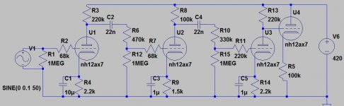
ok ive gone over a few other schematics, asked a few people and thought up a new idea, ive gone back to the 4 gain stage idea but im thinking of using a triode with NFB as the output instead of the usual cathode follower, any comments or ideas on the new schematic will be appreciated!
Thank you for the help so far!
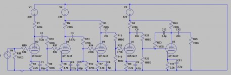
the 780k resistor shown (R25) would be the tonestack and volume control, LTSpice says theoutput here at the gain level shown, is 240vp-p
Thank you for the help so far!
the 780k resistor shown (R25) would be the tonestack and volume control, LTSpice says theoutput here at the gain level shown, is 240vp-p
Attachments
Last edited:
treble mid bass, just a typical marshall style tone stack, a gain after the first gain stage, and a volume after the tone stack
Tone stack and volume all at the end? I dunno, doesn't feel right to me, not the best way to drive the power amp. But I'm not exactly an expert on this stuff

Keep in mind that the tone stack will probably (depending on design) attenuate quite a bit, assuming you'll settle for a passive circuit. A cathode follower after the stack won't provide any gain, so you'll probably be driving the effects loop with a tiny signal.
Also modeling the tone stack as a fixed 780k impedance doesn't seem very realistic to me; I suspect the actual impedance will be a _lot_ lower, and it's probably going to be variable depending on the topology and the position of the controls.
Regarding the gain stages: is there any particular reason to throw away half of the signal after every stage (or even 90% after the third triode)? I'm sure you put some thought into this, but did you simulate the performance of this circuit? Does it seem to work as intended? I'm assuming you're following gingertube's suggestions here, so I'm only checking if the implementation is effective.
Apart from the above, if you're looking for a super-overdriven sound, wouldn't it be a lot easier to just put some diodes back to back, use two gain stages and some frequency shaping? Sort of like a Boss metalzone pedal with tubes?
I"ve modeled the Trainwreck Liverpool tone stack with all settings at noon and it comes out close to 100K impedance.
A cathode follower makes sense to drive a tonestack, as the impedance varies a lot with other settings and will see peaks and dips. It does not make sense following a tonestack. You need a good bit of gain after it because it really attenuates the signal.
I recommend you read "Designing Valve Preamps" by M. Blencowe. It is a great book , even if you don't design guitar amps Good simple explainations and easy to follow math make it a pleasure to read (in my opinion any way).
I've built two Liverpool inspired amps (all Soviet tubes) and they tend to be very noisy due to the high gain. There are a lot of threads on The Amp Garage related to this issue and there seems to be no single simple solution.
basically i was thinking of the effect loop, how much signal out is ideal? 200vpp into a pedal running at 9v doesnt seem right, and i thought a tonestack impedance would be lower. i dont want to use any solid state stuff, cheating...
and as for the attenuation, this is what ive found is about normal, and this design is quite similar to the peavey 6505+ lead channel, thats the sort of sound im looking for. in the simulation this seemed to work as intended, but like i said whats a good signal output to send to the effect loop and how much would the tone stack attenuate the signal?
and as for the attenuation, this is what ive found is about normal, and this design is quite similar to the peavey 6505+ lead channel, thats the sort of sound im looking for. in the simulation this seemed to work as intended, but like i said whats a good signal output to send to the effect loop and how much would the tone stack attenuate the signal?
- Status
- This old topic is closed. If you want to reopen this topic, contact a moderator using the "Report Post" button.
- Home
- Live Sound
- Instruments and Amps
- 12AX7 high gain guitar amp