Wide band attenuation is normal for high gain designs between stages. Although to the degree shown here is a bit much.
Try alternating between high and medium/low/normal gain stages to avoid attenuation and produce some more rich distortion via overdriving the stages somewhat more.
Try alternating between high and medium/low/normal gain stages to avoid attenuation and produce some more rich distortion via overdriving the stages somewhat more.
razorrick - I noticed the same thing that mastadon did "Regarding the gain stages: is there any particular reason to throw away half of the signal after every stage (or even 90% after the third triode)?" believe me, I dont want to discorage you from this project, but you need to read more and simulate less. "The Ultamate Tone" is very good. I cringe when you talk about 400v PtP in a preamp stage.
I don't have any particular competence in building guitar amps. I did mess around with some 12AX7's and a guitar for a while, and I built a rather straightforward PP EL34 amp back in the day (makes me feel old, but this was about 10 years ago. Clock's ticked on, apparently). In my preamp experiments and the readings I did back then and recently as well, I came to realize a couple of things:
- Lots of gain from regular high voltage 12AX7 stages isn't necessarily pleasant. It depends a bit on what you're after, but straight 'out of the box' it's about as harsh as any ugly transistor overdrive. So lots of gain isn't the only thing you're looking for; tone shaping is where it's at.
- Many gain stages with lots of gain in series will definitely distort the signal significantly. That's obvious. But instead of following this 'sledgehammer' approach, it seems to me that overdriving two triodes (one for each half of the signal wave) at a much lower voltage is more efficient and makes it easier to prevent oscillations and excessive noise issues. Heck, maybe even use FETs for voltage gain and feed the signal into squeezed-off triodes running at a plate voltage of 25V or so. See what you can do with just one 12AX7 (2 triodes), a 25V power supply (heaters of both tubes in series) and a handful of small signal FETs.
- But most importantly: have a clear picture in mind what you're looking for, and then find out how other people got there and what the pros and cons of their designs were. I've come to appreciate the simplicity of many of the tube screamer pedals and other effects boxes that are out there. A handful of parts to make lots of noise; hard to beat that.
That's just about my 2cts. right there.
ah i think i see what im missing now, so the 2 stages after the 1st should be alot colder biased, i know simulations arent the best, but im getting results that seem much better. gone back to using the cathode follower after 4 stages, il work out some better attenuation and frequency roll off aswell. i lowered 2 anode resistors to 100k also.
basically i was thinking of the effect loop, how much signal out is ideal? 200vpp into a pedal running at 9v doesnt seem right, and i thought a tonestack impedance would be lower. i dont want to use any solid state stuff, cheating...
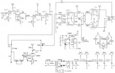
and as for the attenuation, this is what ive found is about normal, and this design is quite similar to the peavey 6505+ lead channel, thats the sort of sound im looking for. in the simulation this seemed to work as intended, but like i said whats a good signal output to send to the effect loop and how much would the tone stack attenuate the signal?
I wanted an effects loop for my high "gain" guitar amp build for reverb/delay type pedals. Those and eq/volume pedals are really the only ones that benefit from a loop. A floor pedal wants to see a guitar level signal going into it. Perhaps 1volt or so max. Much more and it can distort in a bad way. A rack/pro unit can likely accept a stronger signal. I calibrated the max "send" strength in mine by using the clipping indicator on a reverb pedal I have.
I wanted my "send" to be after the preamp clipping that occurs in the 3rd stage. Otherwise the effect in the loop would get squashed (compressed) by the 3rd stage's clipping, defeating the entire purpose of using a loop. Rather than attenuate all the signal down, then bring it all the way back up, I went parallel. I send a small portion to the loop then boost it's "return" up via a triode. This after flipping it's phase back in synce with the "dry" path. I then recombine the loop's return with the strong "dry" signal using a "blend" control. Then on to the PI.
Attachments
Last edited:
- Status
- This old topic is closed. If you want to reopen this topic, contact a moderator using the "Report Post" button.
- Home
- Live Sound
- Instruments and Amps
- 12AX7 high gain guitar amp