I threw the circuit of post #26 together the other day - just to make sure it works. It does. No extensive testing yet, but the plan is to run a pair of my 2x15 3 ways (which dip to 2.6 ohms each in the midrange) and see how it drives them. I added SOA protection using the "standard" circuit. 220 ohms from Re to base, 3.9k (plus steering diode) from base to GND. On the negative side, it needs a 0.22 ohm in one of the output transistor collectors to tap the sense voltage (same as on the PL400/700).
thanks for your helping my friend
watt about TDA7294,TDA7293 and LM3886 with power transistor in out put for more power and 2 ohm load ?http://www.diyaudio.com/forums/chip-amps/206591-tda7294-power-transistors-amp-tda7293-come-also.html
The problem with chip amplifiers, even ones with external boosting transistors, is the limited voltage swing. To get X watts it always requires higher Vcc with a chip amp tnan it does with a discrete solution. With 2 ohm loads, those problems only get worse.
Having all the power, output, and input pins concentrated in one location doesn't lend itself to good circuit layout. It's too easy to get a bad result.
Having all the power, output, and input pins concentrated in one location doesn't lend itself to good circuit layout. It's too easy to get a bad result.
Just because it will take a 2 ohm load and not blow up doesn't mean you should. To deal with a 2 ohm load the circuit needs to be optimized for it. I've never seen a chip amp or chip amp based circuit that was. Low voltage swings, limited rails, too much heat concentrated in one spot, and transistors running out of gain at high currents are all bad.
One other issue that bothers me about the current boosted 7294 amp is that nobody as ever ran it through some heavy tests with results showing from scopes or analyzers.
As I have asked for such results to be posted.
I am sure that it probably sounds okay but to what extent.
This would be hard to tell running PA speakers (and subs) in a club.
That design is running the output devices in Class B with no added bias current and once it starts drawing some current (especially at low ohm loads) I am sure that crossover distortion starts to show up.
I finally got some TDA7294's but I haven't gotten the output transistors yet to finally build the thing and see how it actually performs.
The figures I worked out takes at least three or 4 pairs of output devices to work properly and reliably at 2 ohms, I think I stated that in that thread.
I just built a current boosted opamp amplifier and it works very good but the output voltage swing is indeed limited by the opamp.
At 25Vp-p for a 32v supply, and, only 12Vp-p for a 15V supply.
Also I was using a 4 ohm resistor load to test it with.
It is very simple that uses a LME49860 and a PNP and NPN small signal BJT's and a BD911 and BD912 for the outputs.
From there I may try to adapt it to using an all NPN output banks.
I will do more testing with it once I build a bigger power supply as my goals are the same as yours for driving my ESL's.
Crossover distortion is quite evident as the amplifier starts running out of current on my regulated bench supply.
I still haven't found my other circuit yet but it was based in this JLH design only with lots of 2N3055's, The same as per your requirement,
http://www.diyaudio.com/forums/sili...-headphone-amp-pcb-0-008-thd.html#post2823079
http://www.diyaudio.com/forums/sili...pcb-jlh-2005-class-amplifier.html#post2785105
However, If you were to build this amp for 120 watts it would take about 500 watts to power it because it is a pure Class A design.
It is only 25% efficient and Brdged would get you about 50%.
So, If you bridged two of these than you might get by with about a 250 to 300 watt power supply for 120 watts of output.
However I am not sure how well it would fair for stability and performance at 2 ohms bridged.
I must ask, Why the requirement of 2 ohms?
I have found out first hand that it is not that easy to design such an amp, although not impossible, Just not as easy as one might think and still have a quality performance.
I have blown many 2N3055's in my day from running low impedances on my guitar rig that uses two SUNN Concert slave amps.
It is a bridged design with 4 output devices and although it can put out quite a bit of power the very most that it can used for cleanly is about 70 to 80 watts and then after that it becomes very distorted even before it has reached the clipping level at about 120watts or more as it is rated at 180watts peak (180rms and 360 peak in the older adds for it back in the day).
I just love those amps for there simplicity but by no means are they Hi-Fi quality.
The schematic can be found here,
sunn concert lead schematic - Google Search
As is the Sunn Coliseum amplifier, That was one brute of an amplifier and it uses 3 pairs of outputs as well.
It uses the higher power version of the 2N3055's, The 2N3773's.
I put 2N3773's in my Concert series amps.
I have one other schematic that I just finally found and it is a Randall design very similar to the Sunn Coliseum design I will have to find my sheet and scan it in for you.
I have a friend who had this amp and it came with the schematic and he built a stereo PA system using this design.
I have heard it and it sounded great.
The specs form the manual (that I wrote down) are 120watts 8 ohms,200 watts 4 ohms, 338watts 2ohms and 400watts into 1 ohm, Noise -86db on a +/- 43.5V power supply.
I had also recently stumbled on the schematic on the web as well finally after some 30years and I think it said that it had only .1% THD or so before clipping.
It too uses the 2N3773's but I am sure the 2N3055's will work as well as they are nearly the same.
It is the simplest design I have ever seen and I have had this schematic that long and never built one.
But, Like I said, I have witnessed a DIY version and I was very impressed even by the standards of the early 80's.
I will draw it up in Circuitmaker with all of the details that I have hand copied directly from the original manual and post it for you.
Cheers!!!
jer")
As I have asked for such results to be posted.
I am sure that it probably sounds okay but to what extent.
This would be hard to tell running PA speakers (and subs) in a club.
That design is running the output devices in Class B with no added bias current and once it starts drawing some current (especially at low ohm loads) I am sure that crossover distortion starts to show up.
I finally got some TDA7294's but I haven't gotten the output transistors yet to finally build the thing and see how it actually performs.
The figures I worked out takes at least three or 4 pairs of output devices to work properly and reliably at 2 ohms, I think I stated that in that thread.
I just built a current boosted opamp amplifier and it works very good but the output voltage swing is indeed limited by the opamp.
At 25Vp-p for a 32v supply, and, only 12Vp-p for a 15V supply.
Also I was using a 4 ohm resistor load to test it with.
It is very simple that uses a LME49860 and a PNP and NPN small signal BJT's and a BD911 and BD912 for the outputs.
From there I may try to adapt it to using an all NPN output banks.
I will do more testing with it once I build a bigger power supply as my goals are the same as yours for driving my ESL's.
Crossover distortion is quite evident as the amplifier starts running out of current on my regulated bench supply.
I still haven't found my other circuit yet but it was based in this JLH design only with lots of 2N3055's, The same as per your requirement,
http://www.diyaudio.com/forums/sili...-headphone-amp-pcb-0-008-thd.html#post2823079
http://www.diyaudio.com/forums/sili...pcb-jlh-2005-class-amplifier.html#post2785105
However, If you were to build this amp for 120 watts it would take about 500 watts to power it because it is a pure Class A design.
It is only 25% efficient and Brdged would get you about 50%.
So, If you bridged two of these than you might get by with about a 250 to 300 watt power supply for 120 watts of output.
However I am not sure how well it would fair for stability and performance at 2 ohms bridged.
I must ask, Why the requirement of 2 ohms?
I have found out first hand that it is not that easy to design such an amp, although not impossible, Just not as easy as one might think and still have a quality performance.
I have blown many 2N3055's in my day from running low impedances on my guitar rig that uses two SUNN Concert slave amps.
It is a bridged design with 4 output devices and although it can put out quite a bit of power the very most that it can used for cleanly is about 70 to 80 watts and then after that it becomes very distorted even before it has reached the clipping level at about 120watts or more as it is rated at 180watts peak (180rms and 360 peak in the older adds for it back in the day).
I just love those amps for there simplicity but by no means are they Hi-Fi quality.
The schematic can be found here,
sunn concert lead schematic - Google Search
As is the Sunn Coliseum amplifier, That was one brute of an amplifier and it uses 3 pairs of outputs as well.
It uses the higher power version of the 2N3055's, The 2N3773's.
I put 2N3773's in my Concert series amps.
I have one other schematic that I just finally found and it is a Randall design very similar to the Sunn Coliseum design I will have to find my sheet and scan it in for you.
I have a friend who had this amp and it came with the schematic and he built a stereo PA system using this design.
I have heard it and it sounded great.
The specs form the manual (that I wrote down) are 120watts 8 ohms,200 watts 4 ohms, 338watts 2ohms and 400watts into 1 ohm, Noise -86db on a +/- 43.5V power supply.
I had also recently stumbled on the schematic on the web as well finally after some 30years and I think it said that it had only .1% THD or so before clipping.
It too uses the 2N3773's but I am sure the 2N3055's will work as well as they are nearly the same.
It is the simplest design I have ever seen and I have had this schematic that long and never built one.
But, Like I said, I have witnessed a DIY version and I was very impressed even by the standards of the early 80's.
I will draw it up in Circuitmaker with all of the details that I have hand copied directly from the original manual and post it for you.
Cheers!!!
jer
http://www.tubebooks.org/file_downloads/McIntosh/MC2300.pdf
Just use half the output stage, and ±30V~35V.
Just about anything will work for the small signal transistors.
The MC2300 is 300W into 1Ω from ±40V, should do fine with half the number of outputs into 2Ω at slightly reduced voltage.
http://www.tubebooks.org/file_downloads/McIntosh/MC2100.pdf
Same thing, ±35V, half the number of outputs.
Last edited:
thanks djk but ...
Hi djk
thanks for your help but i can not download and see PDF files.
can you please email them to me ?
Hadi.ghr.e.61@gmail.com
Hadi_ghr_e_61@yahoo.com
thanks my friend
http://www.tubebooks.org/file_downloads/McIntosh/MC2300.pdf
Just use half the output stage, and ±30V~35V.
Just about anything will work for the small signal transistors.
The MC2300 is 300W into 1Ω from ±40V, should do fine with half the number of outputs into 2Ω at slightly reduced voltage.
http://www.tubebooks.org/file_downloads/McIntosh/MC2100.pdf
Same thing, ±35V, half the number of outputs.
Hi djk
thanks for your help but i can not download and see PDF files.
can you please email them to me ?
Hadi.ghr.e.61@gmail.com
Hadi_ghr_e_61@yahoo.com
thanks my friend
Hi Hadighorbani,
Quasi's Nbip amplifier would also serve your purpose well. A number of schematics are already proposed earlier in this thread. Your load is 2 ohm, so i assume that you need a subwoofer amp or for low frequency amplification.
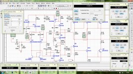
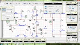
So here's my try for the components you specified. All BC556/546 for input stage, BD139/140 for VAS and predrivers, TIP41C drivers and 2N3055 outputs. It's TEF configuration, LTP runs at 2.5mA, VAS at 8mA, drivers at 20mA and +/-30V supply. It's based on Self's blameless amplifier and is very stable in simulation. THD figures are 0% @100Hz, 0%@1kHz and 0.005%@20kHz 130W into 2R.
Regards,
Aniket
Quasi's Nbip amplifier would also serve your purpose well. A number of schematics are already proposed earlier in this thread. Your load is 2 ohm, so i assume that you need a subwoofer amp or for low frequency amplification.
So here's my try for the components you specified. All BC556/546 for input stage, BD139/140 for VAS and predrivers, TIP41C drivers and 2N3055 outputs. It's TEF configuration, LTP runs at 2.5mA, VAS at 8mA, drivers at 20mA and +/-30V supply. It's based on Self's blameless amplifier and is very stable in simulation. THD figures are 0% @100Hz, 0%@1kHz and 0.005%@20kHz 130W into 2R.
Regards,
Aniket
Attachments
Last edited:
Hi Hadighorbani,
Quasi's Nbip amplifier would also serve your purpose well. A number of schematics are already proposed earlier in this thread. Your load is 2 ohm, so i assume that you need a subwoofer amp or for low frequency amplification.
So here's my try for the components you specified. All BC556/546 for input stage, BD139/140 for VAS and predrivers, TIP41C drivers and 2N3055 outputs. It's TEF configuration, LTP runs at 2.5mA, VAS at 8mA, drivers at 20mA and +/-30V supply. It's based on Self's blameless amplifier and is very stable in simulation. THD figures are 0% @100Hz, 0%@1kHz and 0.005%@20kHz 130W into 2R.
Regards,
Aniket
thanks friend
do you have pcb for test it with ?
thanks friend
do you have pcb for test it with ?
No, there's no PCB, but, I could design a PCB for this amp, if you want?
Nice work Aniket,
Can you please post, multisim file and p.c.b of this.
Hello Sir,
here's the simulation file. PCB is not done yet. would post it soon.
Regards,
Aniket
Attachments
The output configuration of those McIntosh amps is nearly the same as what the Randall amps used.
Thanks for the links as I will put them in my archives as well.
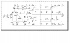
I will have the schematic that I promised for you shortly as I have it drawn up but I have to change the labels on the parts.
I also have a bunch of links to verify that it is the correct drawing as well.
The design that I have is the same basic design that they used in all of there amplifier designs only different variations as you will see.
It is the only variation that I can't seem to find the exact print for.
Just to give you an idea, Here is one of those links and it is the same schematic that I have only I have different parts numbers,
RANDALL RB1000,RB2000 ROAD WARRIOR Service Manual free download, schematics, eeprom, repair info for electronics
jer
Thanks for the links as I will put them in my archives as well.
I will have the schematic that I promised for you shortly as I have it drawn up but I have to change the labels on the parts.
I also have a bunch of links to verify that it is the correct drawing as well.
The design that I have is the same basic design that they used in all of there amplifier designs only different variations as you will see.
It is the only variation that I can't seem to find the exact print for.
Just to give you an idea, Here is one of those links and it is the same schematic that I have only I have different parts numbers,
RANDALL RB1000,RB2000 ROAD WARRIOR Service Manual free download, schematics, eeprom, repair info for electronics
jer
- Status
- This old topic is closed. If you want to reopen this topic, contact a moderator using the "Report Post" button.
- Home
- Amplifiers
- Solid State
- 120 watt amp in 2 ohm loud with 2n3055