You can make an audio amp if requirements are not too severe..
After all , the 3055 quasi complementary amps ended the reign
of tube amps for good...
Are you sure?

2 pair will do it for SOA, but I'd like to get the beta droop down to something reasonable 3055s really aren't bad in that regard since the s/b breakpoint is at 40V, and you wouldn't use them with VCE over 70. TIP41's are nice (enough) for drivers and you can always find some laying around.
Pichers of Coke (Pepsi) aren't good for anything - even nuke plant control panels.
300 W was blowing the dust caps off woofers? Would those Gauss fold up like tissue paper in an SS15?
3055s really aren't bad in that regard since the s/b breakpoint is at 40V, and you wouldn't use them with VCE over 70. TIP41's are nice (enough) for drivers and you can always find some laying around.Pichers of Coke (Pepsi) aren't good for anything - even nuke plant control panels.
300 W was blowing the dust caps off woofers? Would those Gauss fold up like tissue paper in an SS15?
Are you sure?
Yes. Tube amplifiers no longer rule. They will never go away, but the market share is pretty low.
To get 120W / 2 Ohms you need a PSU with output voltages of at least + /-25Vdc.
For example, you can build a power supply that give + /-30VDC (idle) and in the full load, the supply voltage down to + / - (25 ... 27) VDC.
If you are looking for an audio amplifier scheme, then I recommend you use the diagram from the PDF attached below. It is a revision to PSS audio amplifiers made by Yuri G., 4 years ago, on PSS Audio forum. It works very well and supply voltages of +/-30VDC. That scheme can replace MJ15024 with 2N3055.
Attachments
Keep in mind that for 120watts into 2 ohms the current demand will be in the order of 11 amps at 22Vpeak into the load regardless of the power supply voltage.
In any case increasing the number of outputs helps this issue.
But as stated earlier as the current goes up as per device in the output stage each devices current gain goes down.
This requires more current from the driver transistors as well and can easily exceed their maximum power dissipation or current rating as well.
One way around this is to build it so that you have one pair of 2N3055's after the drivers (TIP41's or TIP31/32's or BD139/140's or what ever your using) to drive the large bank of 2N3055's, such as in the phase linear designs as mentioned.
I believe this is what I did in my JLH design simulation (I will look for that schematic sometime tonight).
jer
Exactly. It should work. I would make R1 4.7 ohms (or even 3.3). Adjust R8 - trim the resistor then put in a fixed value, do NOT use a pot - for best differential balance (equal current in Q1 and Q2). It will work with any reasonable value, but it will have lowest distortion when set properly. Adding a current mirror would help here but increase open loop gain and invite stability problems.
If there is a stability problem it likely will NOT blow anything and the usual fixes should clean anything up. Play with Cdom, add 100pF c-b an the predrivers, etc. On lower VCC's like this usually there is no issues. When you go to +/-80V is when things that used to work.... don't anymore.
If there is a stability problem it likely will NOT blow anything and the usual fixes should clean anything up. Play with Cdom, add 100pF c-b an the predrivers, etc. On lower VCC's like this usually there is no issues. When you go to +/-80V is when things that used to work.... don't anymore.
Yes, the outpout RC network can be trimmed.
The differential current balance should be good enough with the values
selected such that no trimmer is needed for the purpose while as you point
it adding a current mirror deacrease stabilty with not that much improvement
linearity wise.
At 1khz THD should be at most 0.02% rising with frequency to 0.1%
at the upper side of the audio extremity but i doubt that this amp will
ever see a full swing at 20khz , wich it can accomodatre despite a 7V/us
slew rate , actualy with the considered devices one can hardly do
higher without running in instability.
3055's are designed for series regulators, not for AUDIO.
They are designed for medium power audio amplifiers and anything else that requires current gain.
There are hundreds of power amplifier designs using 2N3055's or 40636 as quasi complimentary amplifiers and hundreds more using 2N3055 and MJE2955 complimentary amplifiers.
Quite a useful Old School component.
117Watt dissipation at 70Volts C-E with a current gain of 20 - 70.
Here is a old 70's Maplin amplifier that used 2n3055's.
The complimentary was an MJ2955
The complimentary was an MJ2955
An externally hosted image should be here but it was not working when we last tested it.
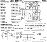
RCA 2N3055H Amplifier.
Here is RCA 2N3055H amplifier,
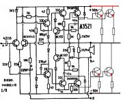
I made it in 1983 with 6 pairs each channel,and used up to 12 nos.12" speakers on one channel direct for open air programmes,All that is needed is a nice heavy duty Transformer with lots of uf capacitors in filter and large finned heatsinks with force cooling, Voltage mentioned 50-0-50 is for RCA2N3055H transistors only, other transistors will tolerate maximum 42-0-42 volt d.c. only.I have included extension diagram also ,one can add more transistors same way.
Here is RCA 2N3055H amplifier,
I made it in 1983 with 6 pairs each channel,and used up to 12 nos.12" speakers on one channel direct for open air programmes,All that is needed is a nice heavy duty Transformer with lots of uf capacitors in filter and large finned heatsinks with force cooling, Voltage mentioned 50-0-50 is for RCA2N3055H transistors only, other transistors will tolerate maximum 42-0-42 volt d.c. only.I have included extension diagram also ,one can add more transistors same way.
Attachments
"Assuming I had enough of them (and that they were free) I would use three in parallel per side and run off a +/-28V supply (20-0-20, 5A toroid). Use TIP41C drivers and 2N5401/5551 predrivers in a TRIPLE. Yes, a triple. The output schematic would look like the Phase Linear 400 with lower rails. It works with low gain transistors like the 3055, will drive 2 ohms, and it's (almost) foolproof. Standard diff pair front end and single ended VAS with a bootstrap (copy from the DX amp, it's as good as you need). "
Basically, I agree.
I would use only two pair of outputs though, and use another pair for drivers. This would look a lot like half the output stage of the McIntosh MC2300, rated at 300W into the 1Ω primary of its output autoformer.
I actually rebuilt an MC2300 with Motorola 2N3055s in the late 70s, they don't work well when you pour a pitcher of Coke into them while running!
After the rebuild, they only problem the club had was the dustcaps blowing off their 15" Gauss woofers.
McIntosh uses 0.33Ω emitter resistors on the outputs, and either 0.56Ω, 0.62Ω or 0.68Ω resistors on the drivers. The predrivers had 100Ω resistors.
You could download a McIntosh MC2100 schematic to see the general idea, although I too would use the DX amplifier front end (Mac used resistors for current sources pulled up to 100V supplies!). The Mac schematic also shows current limiting for short circuit protection.
thanks my friend
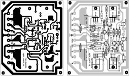
do you have pcb and layout for dx amp with 2n3055 in output ?
anyone have this please ?
thanks too all
To get 120W / 2 Ohms you need a PSU with output voltages of at least + /-25Vdc.
For example, you can build a power supply that give + /-30VDC (idle) and in the full load, the supply voltage down to + / - (25 ... 27) VDC.
If you are looking for an audio amplifier scheme, then I recommend you use the diagram from the PDF attached below. It is a revision to PSS audio amplifiers made by Yuri G., 4 years ago, on PSS Audio forum. It works very well and supply voltages of +/-30VDC. That scheme can replace MJ15024 with 2N3055.
thanks my friend
can i replace mje15034, mje15035 with tip41c and tip42c ?
Keep in mind that for 120watts into 2 ohms the current demand will be in the order of 11 amps at 22Vpeak into the load regardless of the power supply voltage.
In any case increasing the number of outputs helps this issue.
But as stated earlier as the current goes up as per device in the output stage each devices current gain goes down.
This requires more current from the driver transistors as well and can easily exceed their maximum power dissipation or current rating as well.
One way around this is to build it so that you have one pair of 2N3055's after the drivers (TIP41's or TIP31/32's or BD139/140's or what ever your using) to drive the large bank of 2N3055's, such as in the phase linear designs as mentioned.
I believe this is what I did in my JLH design simulation (I will look for that schematic sometime tonight).
jer
thanks body
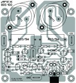
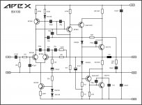
Apex Quasi, from this forum only,
can easily use 2n3055 with this voltage, but offcourse with nice heatsinks and force cooling.
hi dear friend
thanks for your help
one question
why bx100 schematic was difrent with bx layout ?!
schematic have mje15031 but layout dont have it !
thanks
I think that one of the easiest way to reach your goal without a lot of design issues is to parallel some chipamps.
Make sure that you use a DCservo opamp as well to keep them in balance with each other.
Based the PA100 only using 4 chips and the PA150 that uses 3 chips (LM3886) as well as the TDA7293 or TDA7294's can be used as well.
I think the TDA72XX chips may be a better choice as they have a higher current rating for their output stage at about approximately 10amps vs 7amps for the LM3886.
Using the 2N3055's can make a decent amp as well although not today's state of the art with less performance and more THD.
Apex Audio's designs here are pretty much what you may need as posted earlier with about 3 or 4 pairs of output devices as mentioned.
You can also check out Rod Elliotts site for some design ideas as well,
Elliott Sound Products - The Audio Pages (Main Index)
It is a great site and it is very informative and explains the how's and why's of power amplifier design and workings.
He also describes a massive 1500watt into 4 ohm amp and is basically a similar design only he uses both, NPN and PNP devices, in the output stage.
A wide variety of output devices will work in the Apex design, I have thought about such a beast myself.
That is what the schematic I posted was derived from "The Apex design" and my plan was to use a bunch of 2N3055's as well or the 2N3772's or 2N3773's.
But, They are now becoming more harder to find now and actually cost more than the better (more modern) version's such as the 2SC5200.
The MJE15031 and its compliment is basically a newer higher quality, higher voltage (Vceo at 150V vs 100V) version of the old Tip32c (PNP) and TIP31c (NPN).
And the TIP42's that you have are basically a higher power version of the Tip32's.
Here are the data sheets for you to compare them,
http://www.onsemi.com/pub_link/Collateral/MJE15028-D.PDF
https://www.fairchildsemi.com/ds/TI/TIP42.pdf
http://pubpages.unh.edu/~aperkins/pdf/TIP-devices/TIP31.pdf
jer
Last edited:
I threw the circuit of post #26 together the other day - just to make sure it works. It does. No extensive testing yet, but the plan is to run a pair of my 2x15 3 ways (which dip to 2.6 ohms each in the midrange) and see how it drives them. I added SOA protection using the "standard" circuit. 220 ohms from Re to base, 3.9k (plus steering diode) from base to GND. On the negative side, it needs a 0.22 ohm in one of the output transistor collectors to tap the sense voltage (same as on the PL400/700).
- Status
- This old topic is closed. If you want to reopen this topic, contact a moderator using the "Report Post" button.
- Home
- Amplifiers
- Solid State
- 120 watt amp in 2 ohm loud with 2n3055