Isn't that the infamous one that just plain doesn't work (due to undefined idling currents)? I'm not sure it's a good idea to even show that circuit as a bad example in case some poor sucker feels tempted to build it.Here is a typical simple Sloan design.
Then we end up with another thread like this: http://www.diyaudio.com/forums/solid-state/165530-heeeelllppp-m-randy-slone-mirror-image-topology-construction-troubles.html. Actually, I think Olivier just enjoys pain - He's been trying to get that thing to work since April last year, and hasn't given up yet.
That's destroyer X, well known designer, builder and blower-up of amplifiers.Who's uncle Charlie?
Please don't!...and I don't know if I should bother with his 50 Watts RMS "professional grade amplifier"...
OK wait, to be fair, I suppose I should at least look at the circuit before condemning it out of hand. (Or maybe it's just out of morbid curiosity that I'm tempted to have a look).
Seriously, there's lots of tried and tested amp designs on this forum that work properly and sound good. Destroyer X's designs, for example, are very highly regarded by the many people that have built them.
IMO, a big advantage to building something published here is that you have a lot of support from others who are building (or have built) the same thing.
P.s. My favorite "uncle Charlie" quote:

It is interesting, very interesting it has a personality, a personal character while
burning, it goes in flames, yellow flames, when other pops a blue ligth and the transistor case is opened with a clear hole or a slice is busted!
Also the unit burns the stop resistors...i do not know if those resistances are too much weak (new ones i have received from Greece) but they carbonize easy and smells a lot.
The amplifier seems not to have a good mood when i ask high levels nearby the clipping levels.
At this moment it is into the repair table, i am waiting the sunrise to fix.... home ligth is not very good for that, also my head produces shadows.... waiting for the sun.
regards,
Carlos
Mikedrz is really a very interesting guy
Ahahahahah.
People use to say tha time travell to the past is impossible... a Paradox because you can kill your father before you born..how can this be possible?
This friend show me that is possible...other man. other body...doing the same we did...a travell to the past.
Welcome buddy
Carlos
Ahahahahah.
People use to say tha time travell to the past is impossible... a Paradox because you can kill your father before you born..how can this be possible?
This friend show me that is possible...other man. other body...doing the same we did...a travell to the past.
Welcome buddy
Carlos
Last edited:
Ahahahahah.
Welcome buddy
Carlos
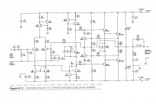
Howdy, and thanks for the warm welcome! I've attached a schematic of the "professional 50 Watt Amplifier"
I've etched the board, but the copy didn't come out clean so I've got to scrape some of the copper off where paths are shorting. What do you guys think of this design? Will it work off of my cheesy power supply using my 2 24VAC transformers in series?
Would appreciate any input,
Cheers!
Attachments
Just that.... a very good audio amplifier....this is a Blameless style amplifier...unbeatable!
regards,
Carlos
Thank you for your blessing, I will look at some of your designs after gaining a little more knowledge. The cold canadian winter is on its way, and I will have plenty of time to develope cabin fever. Haha. I am sure I will be reaching out for help when things go wrong.
I can see no major inherent flaws with this design. Should be fine for 50 W / 4 ohms or so, as intended. It's a fairly standard topology, with some extra protection added. There's only two things I might change:
1. C1 and C2 form a makeshift replacement for a real bipolar cap.
2. Accurate quiescent current setting may be difficult without a multiturn pot. Bad contact in the pot would also cause the quiescent current to increase, potentially up to problematic levels.
If I'm not mistaken, P1 would typically be set at about 1/4 its nominal value. I'd split this into a series fixed R - pot - fixed R combo, so you can adjust Q9's base-emitter voltage between maybe 1/3 and 1/5 its collector-emitter voltage. The pot and one fixed R go between base and emitter, the other fixed R is on the collector side. The pot's wiper is connected to one of its ends, so you get a two-terminal variable resistor. Should wiper contact ever fail, pot R would go to max, Q9 C-E voltage would go to min and so would output stage bias current. (This arrangement is fairly standard in '90s and later amps.)
Your two 20 VAC xfmrs with secondaries connected in series (>=50..100 VA each?) should be just fine, don't forget to connect the common line to ground though. In terms of electrolytics, something like 6800µ 50/63V would be standard.
As for current limiting via Q12/13... it should be fine (and not yet do anything) for at least 5Apk, which happens to be the equivalent of 50 W / 4 ohm. One may want to modify resistor divider values for a slightly higher value, while taking care not to set threshold too high. Otherwise it's "reading up on how to keep things in SOA in a more advanced way" time.
Last edited:
HiBuilding things like that cob-web could make you uncle Charlie's next best friend.....(Slone)..had the tendency to chuck a whole bucket full of components into it, some for no good reason at all, just so it would look complex. So I would support your opinion.
Some would agree there after trying to emulate the "Hellllllllp!" thread design that's dragged on forever on this forum. However, there are plenty who have been grateful for his contributions in an era when no other books besides Self's were around as guidance for would-be audio tinkerers. I know several people who have built his simpler designs successfully and obtained the quoted response performance figures without fuss. You can all turn up your noses and pooh-pooh his designs for that particular error (relying on Multisim I suspect!) but I even built a simpler one many years ago as a 400W P.A.for a club. Yes, it worked from first power up with just 220 ohm safety resistors. It was still working recently as the main hall amp. with completely new console and speaker system so it is reliable
This is the main thrust of his designs. They are sure not high-end or Hi-Fi designs but intended for knocks, bumps and instruments or vocal. It always seemed obvious to me and he makes that clear in his Construction Manual.
Let me assure you, his designs are less verbose than those US commercial designs he targeted as benchmarks, regardless of the symmetric input stage and balanced VAS etc. I think we err in measuring his stuff against the bare-bones home hi-fi we tend to focus on. It's interesting to read that his justification for symmetric input stages is to avoid loud disturbance when plugging in Microphones or line feeds "hot". 'Quite out of the question for us, but highly likely when untrained persons do this repeatedly with live PA gear.
BTW, Anyone experienced with audio should have twigged to the motorboating clue in the 1Hz pulsing first. It indicates overcoupling around any amp and poor wiring or layout usually. As we find, the answer is in both.
Very nice! I take back my rude comments earlier.I've attached a schematic of the "professional 50 Watt Amplifier"...
What do you guys think of this design?
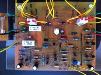
Hello folks, I'm back as I knew I would be. I have finished the 50W Amp.
I've hooked it up to a the power supply and nothing went up in smoke and no components were overheating. However when I was measuring voltages, it doesn't seem right. The speaker output has 35.8 volts DC across it. I am using the common and not the "signal common". This was done with no input or output connected. I'm wondering if i've measured incorrectly, or if there is a short somewhere.
When I measured the signal IN voltage I got 0.9 V DC. Almost every component I've measure has 35 or 36 volts across it with respect to common.
I don't want to connect an audio source or speaker to it, fearing they might blow. Any suggestions?
Attachments
Your signal common should connect to the amplifier ground through a 10 ohm resistor. Have you got this connection? The schematic does not show this and therefore your amp output will swing to a rail.
Hey Nico Ras, I've built it in as it is in the schematic, you're saying that the signal common should goto the amps common through a 10 K resistor? R1 is a 10 K resistor, there is another 10K resistor, that goes to ground, but it goes through the first pair of resistors.
Nico, thank you. That is exactly what it was. I ran signal common directly to the ground of the power supply and it works. This book is not very beginner friendly even though it prides itself of that. It's all the way at the back, that they mentioned this important step, that they didn't put into the schematic.
Now I have another challenge, I want to use this as a mono amp, but how do I combine two stereo channels into one; instead of just listening to either left or right?
Now I have another challenge, I want to use this as a mono amp, but how do I combine two stereo channels into one; instead of just listening to either left or right?
Are you looking to increase power into the load? If so then you'd likely be looking to use them in a bridged configuration.
Amplifier 'A' would be non-inverting and drives the speaker + terminal and amplifier 'B' is inverting and drives the speaker - terminal. Generally you would invert amplifier 'B's input signal prior to the input with an inverting buffer at line level.
This effectively increases the available voltage swing across the load. Each amplifier will effectively 'see' half of the rated impedance of the load, i.e. an 8 ohm speaker looks like a 4 ohm speaker to the bridged amplifiers. Ignoring losses this would in theory quadruple the power, but realistically one could expect 2-3 times the power dependant on how capable the power supply and amplifiers are.
I'm sorry, my description wasn't very clear. This amp only has one channel, but I have a 3.5mm stereo jack for the input, I'm looking for a way to combine both channels into one, at the input stage. I don't know how to wire it this way, or if I can wire it this way without damaging the source.
Would I need any additional equipment to do this, where would I need to solder with respect to the 3 lugs on the jack? Would I need anymore passive components?
Thanks in advance for any input, I am sort of clueless on how to go about this. haha
Would I need any additional equipment to do this, where would I need to solder with respect to the 3 lugs on the jack? Would I need anymore passive components?
Thanks in advance for any input, I am sort of clueless on how to go about this. haha
Easiest is just to blend the two channels with a couple of resistors. Most line level sources should be happy with resistors of at least 10K. If it's connected to a headphone output, you can go much lower.
For a socket, common/ground is the metal part around the hole the plug goes into. For chassis-mounting sockets, it's the part that touches the chassis.
For a plug, the tip and ring are left and right (I forget which is which), and the part furthest from the tip is common/ground.where would I need to solder with respect to the 3 lugs on the jack
For a socket, common/ground is the metal part around the hole the plug goes into. For chassis-mounting sockets, it's the part that touches the chassis.
Attachments
Easiest is just to blend the two channels with a couple of resistors. Most line level sources should be happy with resistors of at least 10K. If it's connected to a headphone output, you can go much lower.
For a plug, the tip and ring are left and right (I forget which is which), and the part furthest from the tip is common/ground.
For a socket, common/ground is the metal part around the hole the plug goes into. For chassis-mounting sockets, it's the part that touches the chassis.
Thanks, this picture really helps. I'm learning a lot from you guys. Its always the simplest things that are the hardest to find an answer for, or so it seems.
I am going to solder the resistors directly to the tip and ring lugs of the jack, and the bottom or common goes to signal common. 1/4 watt resistors should be fine? I am using an mp3 player headphone out as the source.
Last edited:
I'm sorry, my description wasn't very clear.
Sorry, my interpretation was incorrect. After re-reading your post I now see what you are after. Ian and Godfrey have it, just use resistors to passively combine the signals will work fine. Using 1/4 watt will be more than enough as line level signals (or even a headphone amp) are relatively low voltage and wont produce any real power into 10K resistors.
- Status
- This old topic is closed. If you want to reopen this topic, contact a moderator using the "Report Post" button.
- Home
- Amplifiers
- Solid State
- 12 Watt amp, guidance required